Method of producing blood processing circuits and filter unit

a technology of filter unit and processing circuit, which is applied in the field of producing blood processing circuit and filter unit, can solve the problems of waste of in-line filter, inconvenient handling of in-line filter, and system bulkiness as a whole, and achieves the effects of preserving the performance of filter medium, ensuring connection of tubes, and preserving the rate of removal of specific components

Active Publication Date: 2007-02-22
TERUMO KK
View PDF19 Cites 30 Cited by
  • Summary
  • Abstract
  • Description
  • Claims
  • Application Information

AI Technical Summary

Benefits of technology

[0046] The filter unit according to the present invention should preferably be one which is sterilized by gas sterilization or radiation sterilization. Sterilization in this manner preserves the performance of the filter medium and keeps high the rate of removal of specific components.
[0047] According to the present invention,

Problems solved by technology

First, the in-line filter is inconvenient to handle and makes the system bulky as a whole, although it functions as a constituent of the closed system in which the circuit, filter, and bag are so connected as to permit aseptic blood treatment.
Second, the system has to be discarded together with an intact in-line filter when collected blood is judged to be inadequate for blood products for quantitative or qualitative reasons and hence is discarded.
This wastes the in-line filter.
Third, the system does not permit blood separation and storage without removal of white blood

Method used


Image

  • Method of producing blood processing circuits and filter unit
  • Method of producing blood processing circuits and filter unit
  • Method of producing blood processing circuits and filter unit

Examples


first embodiment

1. The First Embodiment

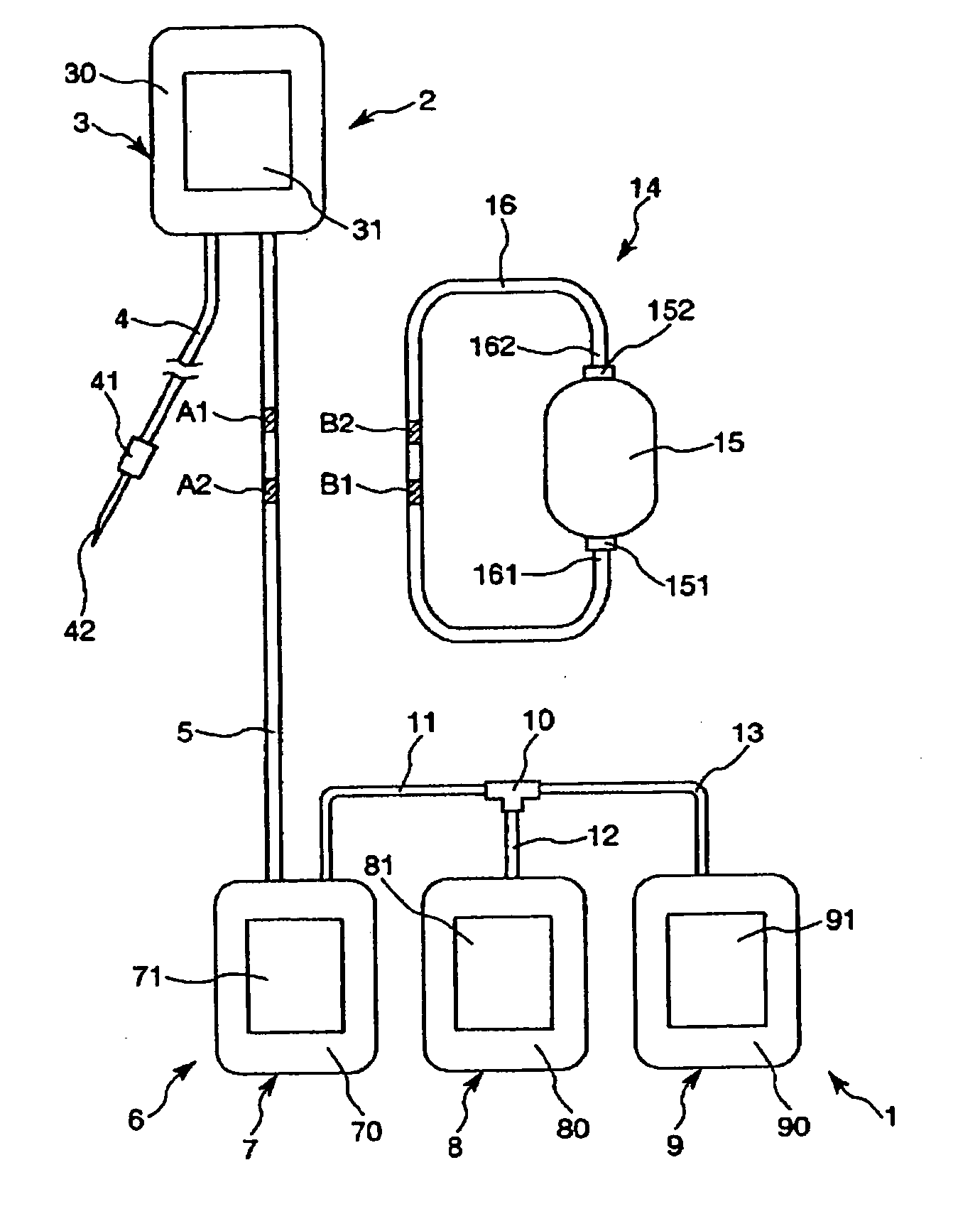
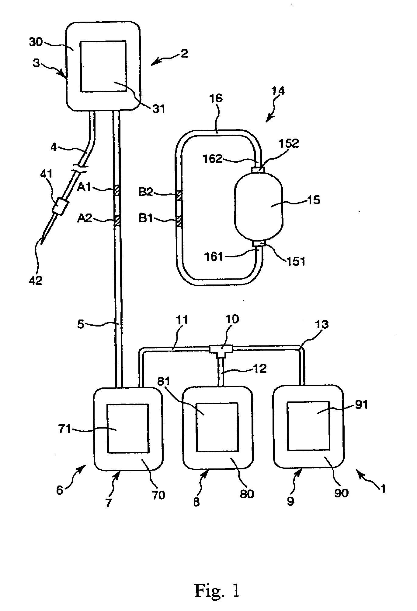
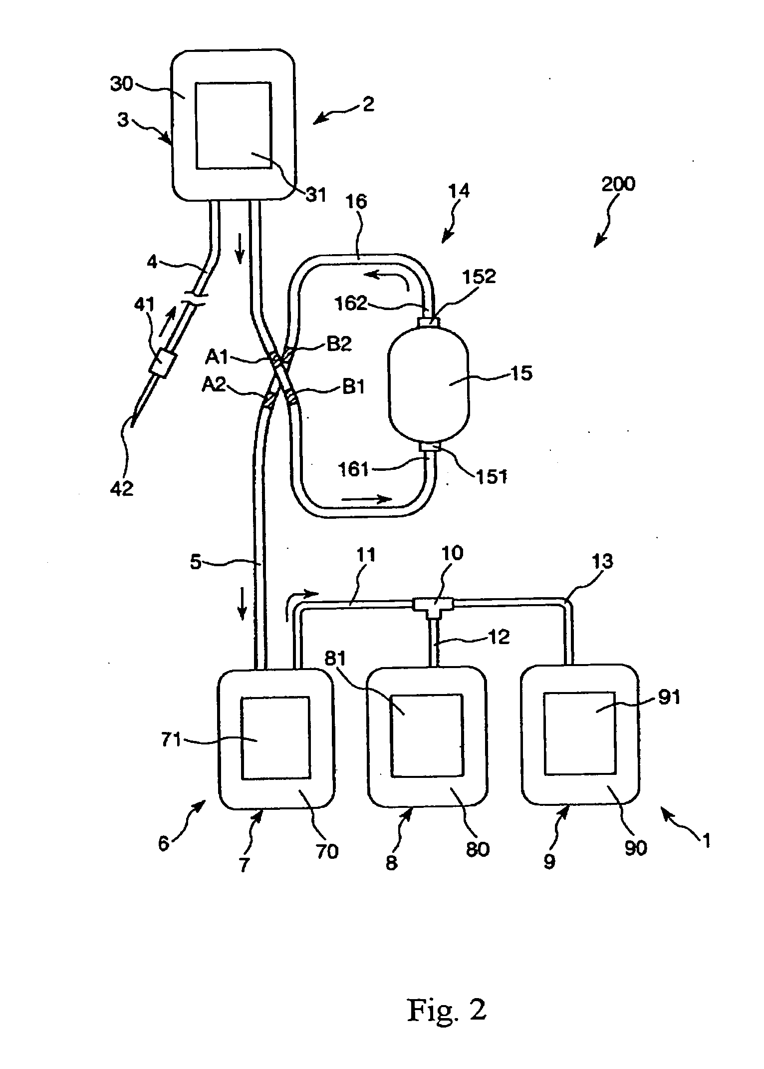
[0060]FIG. 1 is a schematic plan view showing a filter unit and a method for assembling a blood treatment circuit incorporated with the filter unit in the first embodiment of the present invention. FIG. 2 is a schematic plan view showing a blood treatment circuit assembled by the method for assembling a blood treatment circuit according to the first embodiment of the present invention.

[0061] According to the method of the present invention, the blood treatment circuit 200 is assembled by aseptically connecting the tube of the filter unit 14 to the tube of the connected bag set (blood treatment set) 1, so that the filter unit 14 is incorporated into the connected bag set 1 and the blood treatment circuit 200 is obtained as desired.

[0062] The connected bag set 1 and the filter unit 14 are constructed as follows.

[0063] The connected bag set 1 has the blood collecting part 2 and the blood treatment part 6, which are connected to each other by the first tube 5 b...

second embodiment

2. The Second Embodiment

[0140]FIG. 3 is a schematic plan view showing a method for assembling a blood treatment circuit in the second embodiment of the present invention. The difference between the first and second embodiments is described below, with common items omitted.

[0141] The second embodiment is identical with the first embodiment except for the arrangement of the tube to connect the secondary bags 7 and 8 of the connected bag set 1.

[0142] In the first embodiment, one end of the tube 11 is connected directly to the secondary bag 7, whereas in the second embodiment, one end of the tube 11 is connected to the three-way branching connector 17 (T-tube, Y-tube, or three-way cock) which is placed along the tube 5 and one end of the tube 11 (the third tube) is connected to one port of the branching connector 17.

[0143] The second embodiment is identical with the first embodiment in the constitution of the filter unit 14 and the method of assembling the blood treatment circuit 200...

third embodiment

3. The Third Embodiment

[0144]FIG. 4 is a schematic plan view showing a filter unit and a method for assembling a blood treatment circuit incorporated with the filter unit in the third embodiment of the present invention. FIG. 5 is a schematic plan view showing a blood treatment circuit assembled by the method for assembling a blood treatment circuit according to the third embodiment of the present invention. The difference between the second and third embodiments is described below, with common items omitted.

[0145] The third embodiment is identical with the second embodiment except for the position at which the filter unit 14 is connected to the connected bag set 1. (What is mentioned for the first embodiment is applied to the third embodiment.)

[0146] In the first and second embodiments, the filter unit 14 is connected to the tube 5 (the first tube) at its middle point, whereas in the third embodiment, the tube 13 (the third tube) and the tube 16 are aseptically connected to each ...


PUM


Abstract

A bag connection comprises a first bag, a tube having a blood-drawing needle at the front end, a plurality of second bags, tubes for connecting the first and second bags,.and tubes and branch connectors for connecting the second bags to each other. On the other hand, a filter unit includes a filter, and a tube connected at opposite ends thereof to the inlet and outlet of the filter. The tubes of the bag concatenation and the tube of the filter unit have respective markers attached thereto. With these markers used as marks, both tubes are aseptically connected by a tube aseptic connection device, thereby incorporating the filter unit into an intermediate portion of a tube of the bag concatenation.

Description

TECHNICAL FIELD [0001] The present invention relates to a method for assembling a blood treatment circuit which is designed to treat blood collected from a donor. It relates also to a filter unit. BACKGROUND ART [0002] There is known a blood bag system for centrifugal separation of whole blood collected from a donor into three kinds of blood cell products for blood transfusion, which include concentrated red blood cell (CRC), platelet concentrated (PC), and platelet-poor plasma (PPP). [0003] Such blood cell products for blood transfusion often undergo, after separation and storage, a process of removing white blood cells immediately before transfusion into a patient in order to avoid side effects induced after blood transfusion by contamination with white blood cells. [0004] However, it is known that blood obtained by blood donation gives high-quality blood cell products for blood transfusion if it is freed of white blood cells before separation and storage. In order to remove white...

Claims


Application Information

Patent Timeline
IPC IPC(8): A61M37/00A61B19/00A61M1/02A61M39/16
CPCA61M1/3633A61M39/16A61M1/0222A61M1/0231
Inventor SUGAWARA, HIROYUKI
Owner TERUMO KK
Why Eureka
Try Eureka