Radio frequency textile drying machine

Inactive Publication Date: 2007-03-01
FALMER INVESTMENTS LTD
View PDF9 Cites 41 Cited by
  • Summary
  • Abstract
  • Description
  • Claims
  • Application Information

AI Technical Summary

Benefits of technology

[0011] In one embodiment, the radio frequency power generator is connected to the spindle such that the spindle acts as an anode for the purpose of generating the electric field. Consequently, the wall of the tank therefore acts as the cathode. Preferably, the wall is connected to electrical ground. This gives good electromagnetic shielding without the need for dedicated shields to be provided around the machine.
[0012] The radio frequency power generator may be a solid-state radio frequency power generator. Solid-state radio frequency generators have much greater operating lifetimes than conventional electron tube generators, so maintenance costs are reduced. Efficiency is also better.
[0013] According to one embodiment, the radio frequency power generator comprises a driver unit operable to generate a radio frequency signal and one or more amplifier units operable to receive the radio frequency signal from the driver unit and amplify the radio frequency signal. This modular design allows for improved and simplified maintenance, since the units can be serviced and replaced individually. Such a design also gives the high power necessary for textile drying in a convenient format that avoids or reduces many heat generation problems. Air cooling is sufficient; this is preferable to water cooling.
[0014] The radio frequency power generator may further comprise a divider unit operable to receive the radio frequency signal from the driver unit and distribute it bet

Problems solved by technology

A disadvantage of using electron tubes for RF drying is that they are prone to cause a relatively high level of electromagnetic interference in telecommunication devices.
This has many undesirable effects, such as jeopardizing air flight communication.
The interference is caused by leakage of the RF wave from openings in

Method used


Image

  • Radio frequency textile drying machine
  • Radio frequency textile drying machine
  • Radio frequency textile drying machine

Examples


Example

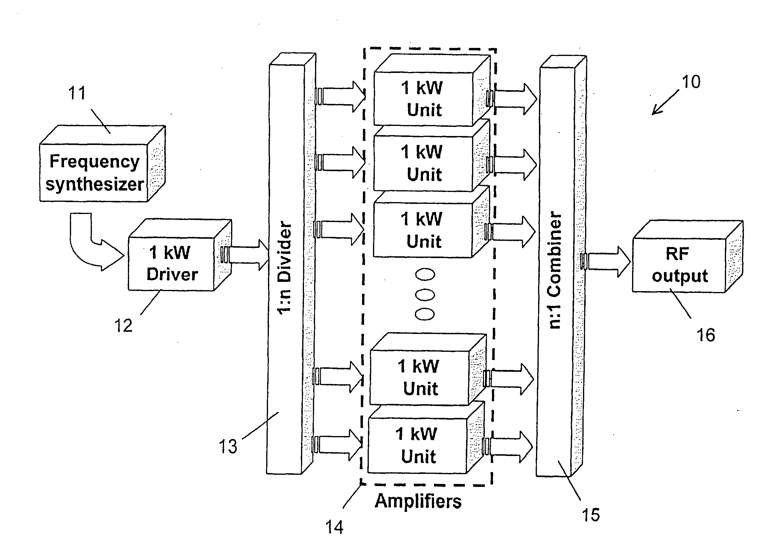
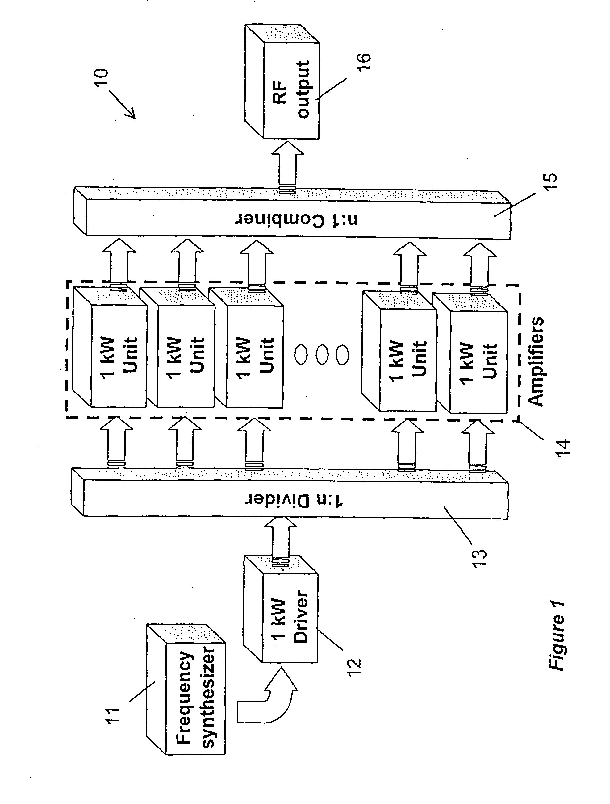
[0027] The present invention proposes a new design of apparatus or machine for drying textiles using high power radio frequency electric fields. The drying capability offered by machines according to the invention allows compact and safe machines to be provided. Moreover, the design of the machine is such that textile dyeing and drying can be carried out in a single machine.

[0028] After textiles are dyed (or otherwise wetted in alternative processing techniques) they need to be dried. Radio frequency (RF) power is commonly used to drying, but textile drying using RF frequencies requires high powers. These maybe obtained using electron tubes to generate the RF wave, but electron tubes, and the designs of proposed drying machines proposed that use them, have disadvantages. An alternative to the electron tube is solid-state technology. This is commonly used to generate RF waves for telecommunications applications, such as mobile telephones and wireless networks. However, these operate...


PUM


Abstract

A textile drying machine comprises a tank for receiving textiles with a spindle inside the tank for supporting the textiles, and a solid-state radio frequency generator. The generator is connected to the spindle and the tank is earthed so that when the generator is operated an oscillating electric field is generated between the spindle and the tank, and hence applied to textiles on the spindle. The electric field heats water molecules in the textiles by molecular vibration so that evaporation occurs, and the water vapor is removed from the tank by an extractor fan. The machine may also be used to dye the textiles prior to drying, thus providing an integrated dyeing/drying machine.

Description

BACKGROUND OF THE INVENTION [0001] The present invention relates to a machine that uses radio frequency waves for drying textiles. [0002] Radio frequency (RF) energy can be used to dry dielectric materials such as textiles. The principle of using radio waves for drying is to apply an electric field oscillating at a radio frequency to the material. This excites molecular vibration at the oscillation frequency in the molecules of the material, which gives an internal heat gain by means of inter-molecular friction. If the material is wet, the heat gain causes the water molecules in the material to undergo a phase change from liquid to gas when enough energy has been absorbed. The gas phase water molecules are then free to escape from the material by evaporation so that the material becomes dry. The amount of heat required to evaporate a unit weight of water is a fixed quantity at a constant pressure. The total amount of heat required to raise the water from a given temperature to evapo...

Claims


Application Information

Patent Timeline
IPC IPC(8): H05B6/60
CPCD06F58/266H05B6/62F26B13/003F26B3/347
Inventor TSUI, WILLIAM TAK MINGIP, RALPH WAI LAM
Owner FALMER INVESTMENTS LTD
Why Eureka
Try Eureka