Piezoelectric substrate, piezoelectric element, liquid discharge head and liquid discharge apparatus

Inactive Publication Date: 2007-03-01
CANON KK
View PDF23 Cites 45 Cited by
  • Summary
  • Abstract
  • Description
  • Claims
  • Application Information

AI Technical Summary

Benefits of technology

[0011] In view of the above identified circumstances, it is therefore an object of the present invention to provide a piezoelectric substrate that shows a controlled crystallinity and an enhanced level of orientation to realize excellent piezoelectric characteristics and produces an enhanced level

Problems solved by technology

However, it is difficult to produce PZT type oxide films with a thickness of not greater than 10 μm by means of the method disclosed in Japanese Patent Application Laid-open No.
Additionally, since such green sheets are sintered at a temperature level not lower than 1,000° C., there arises a problem that the piezoelectric films shrink to 70% of the original size.
Then, it is difficult to align a piezoelectric film and a structure such as an ink chamber with an accuracy level of several microns.
Thus, no satisfactory micro piezoelectric elements have been available to date.
Furthermore, the influence of the crystal grain boundaries becomes unnegligible as ceramic piezoelectric films formed by sintering green sheets show a reduced thickness to consequen

Method used


Image

  • Piezoelectric substrate, piezoelectric element, liquid discharge head and liquid discharge apparatus
  • Piezoelectric substrate, piezoelectric element, liquid discharge head and liquid discharge apparatus
  • Piezoelectric substrate, piezoelectric element, liquid discharge head and liquid discharge apparatus

Examples


example 1

[0072] Firstly, a vibration plate was prepared by forming a film of stabilized zirconia YSZ (Y2O3—ZrO2) on an open section of an Si substrate by means of a sputtering system (L-210-FH (available from ANELVA)). In this process, the Si substrate was heated to 800° C. and Ar and O2 were used as gas to be ionized. Electric power of 100 W was applied between the Si substrate and the target and the internal pressure of the system was held to 1.0 Pa. As a result, a 200 nm thick uniaxial vibration plate was obtained.

[0073] Then, a process same as that of preparing the vibration plate was used to prepare a lower electrode. In this process, Pt was used as target and the substrate was heated to 600° C., while Ar was used as gas to be ionized. Electric power of 100 W was applied between the vibration plate and the target and the internal pressure of the system was held to 0.5 Pa. As a result, a 400 nm thick highly uniaxial Pt film was obtained.

[0074] Subsequently, films of two different oxide...

example 2

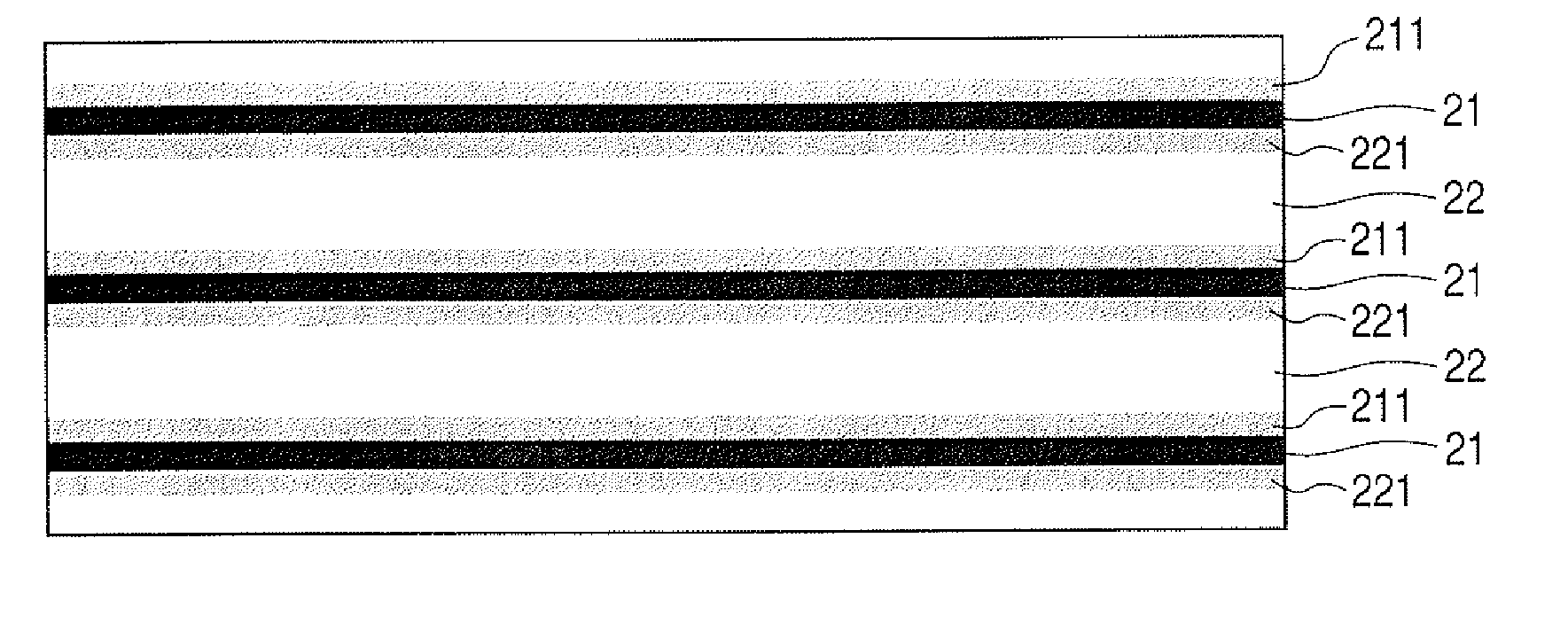
[0079] A liquid discharge head was prepared by following the process of Examples 1 and 2 except that the target compositions as listed below were used for preparing the piezoelectric substrate and a target as illustrated in FIG. 6 was used. As shown in FIG. 6, the target compositions (1) through (3) were arranged in the respective target regions formed by dividing the target by three as materials of the piezoelectric substrate. The sputtering time was 15 minutes, 13 minutes and 11 minutes for the three regions of the different compositions and 4 minutes were spent to form a boundary layer, while moving the aperture of the shutter from one of the compositions to the other. As a result, a piezoelectric substrate comprising 20 layers of the tetragonal structure and 20 layers of the rhombohedral structure and 20 MPB layers that were mixed layers of the two structures was obtained. Thus, it is possible to form a piezoelectric boy having different film thicknesses for layers of different ...

example 3

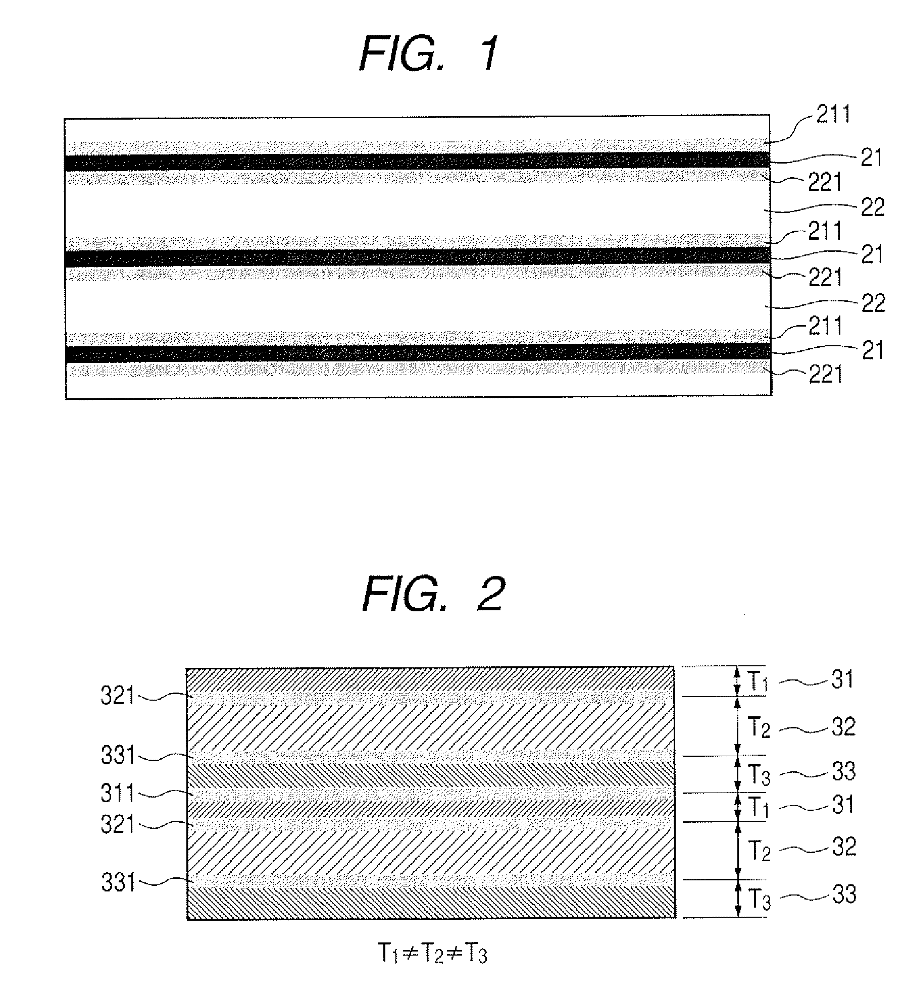
[0082] A liquid discharge head was prepared by following the process of Examples 1 and 2 except that the target compositions (1) through (4) as listed below were used for preparing the piezoelectric substrate and a target where the materials of the piezoelectric substrate were arranged in the respective target regions formed by dividing the target by four. The sputtering time was 24 minutes, 24 minutes, 24 minutes, 30 minutes, 24 minutes and 36 minutes for the regions of the different compositions and 6 minutes were spent to form a boundary layer, while moving the aperture of the shutter from one of the compositions to the other. As a result, a piezoelectric substrate comprising 10 layers of each of the six structures including the tetragonal structure, the rhombohedral structure, the tetragonal structure, the pseudocubic structure, the tetragonal structure and the monoclinic structure was obtained. Thus, it is possible to form a piezoelectric substrate having desired film thickness...


PUM


Abstract

A piezoelectric substrate of a perovskite-type oxide is expressed by a general formula of ABO3 having a laminate structure of a single crystal structure or a uniaxial crystal structure expressed by (Pb1-xMx)xm(ZryTi1-y)O3 (where M represents an element selected from La, Ca, Ba, Sr, Bi, Sb and W) and the laminate structure has a layered first crystal phase having a crystal structure selected from the tetragonal structure, the rhombohedral structure, the pseudocubic structure and the monoclinic structure, a layered second crystal phase having a crystal structure different from the crystal structure of said first crystal phase and a boundary layer arranged between said first crystal phase and said second crystal phase with a crystal structure gradually changing in a width direction of layer.

Description

BACKGROUND OF THE INVENTION [0001] 1. Field of the Invention [0002] The present invention relates to a piezoelectric substrate, a piezoelectric element and a liquid discharge head to be used for a liquid discharge apparatus and also to methods of manufacturing the same. More particularly, the present invention relates to a high density piezoelectric element having a large area and a liquid discharge head using such an element. [0003] 2. Description of the Related Art [0004] There is an increasing demand for long printing heads to be used in ink jet printers in order to improve the resolution and the printing speed of such printers. For this reason, there is a demand for micronized multi-nozzle head structures. Then, piezoelectric elements for discharging liquid are required to be downsized in order to micronize liquid discharge heads. Then, piezoelectric substrates showing a high piezoelectric constant are required in order not to reduce the drive power if liquid discharge heads are...

Claims


Application Information

Patent Timeline
IPC IPC(8): H01L41/187
CPCB41J2/161Y10T29/42B41J2/1642B41J2/1646B41J2202/03C04B35/491C04B2235/3208C04B2235/3215C04B2235/3227C04B2235/3258C04B2235/3294C04B2235/3298C04B2235/76C04B2235/762C04B2235/765C04B2235/768H01L41/18B41J2/1634H10N30/85H10N30/8554
Inventor MATSUDA, TAKANORIIFUKU, TOSHIHIRO
Owner CANON KK
Why Eureka
Try Eureka