
Auto-focusing device with voice coil motor for position feedback and method for using same

a technology of voice coil motor and auto-focusing device, which is applied in the direction of camera focusing arrangement, printers, instruments, etc., can solve the problems of increasing drive efficiency and saving power consumption, and achieves the effects of reducing cost, simple configuration, and small siz

Inactive Publication Date: 2007-03-01
POWERGATE OPTICAL INC
View PDF7 Cites 136 Cited by
  • Summary
  • Abstract
  • Description
  • Claims
  • Application Information

AI Technical Summary

Benefits of technology

[0008] The primary object of the present invention is to provide an auto-focusing device with voice coil motor for position feedback, which uses a magnetic sensor to detect the lens position for position feedback during auto-focusing. The present invention features fewer components, simple configuration, small size, lower cost, positioning precision, and low noise.
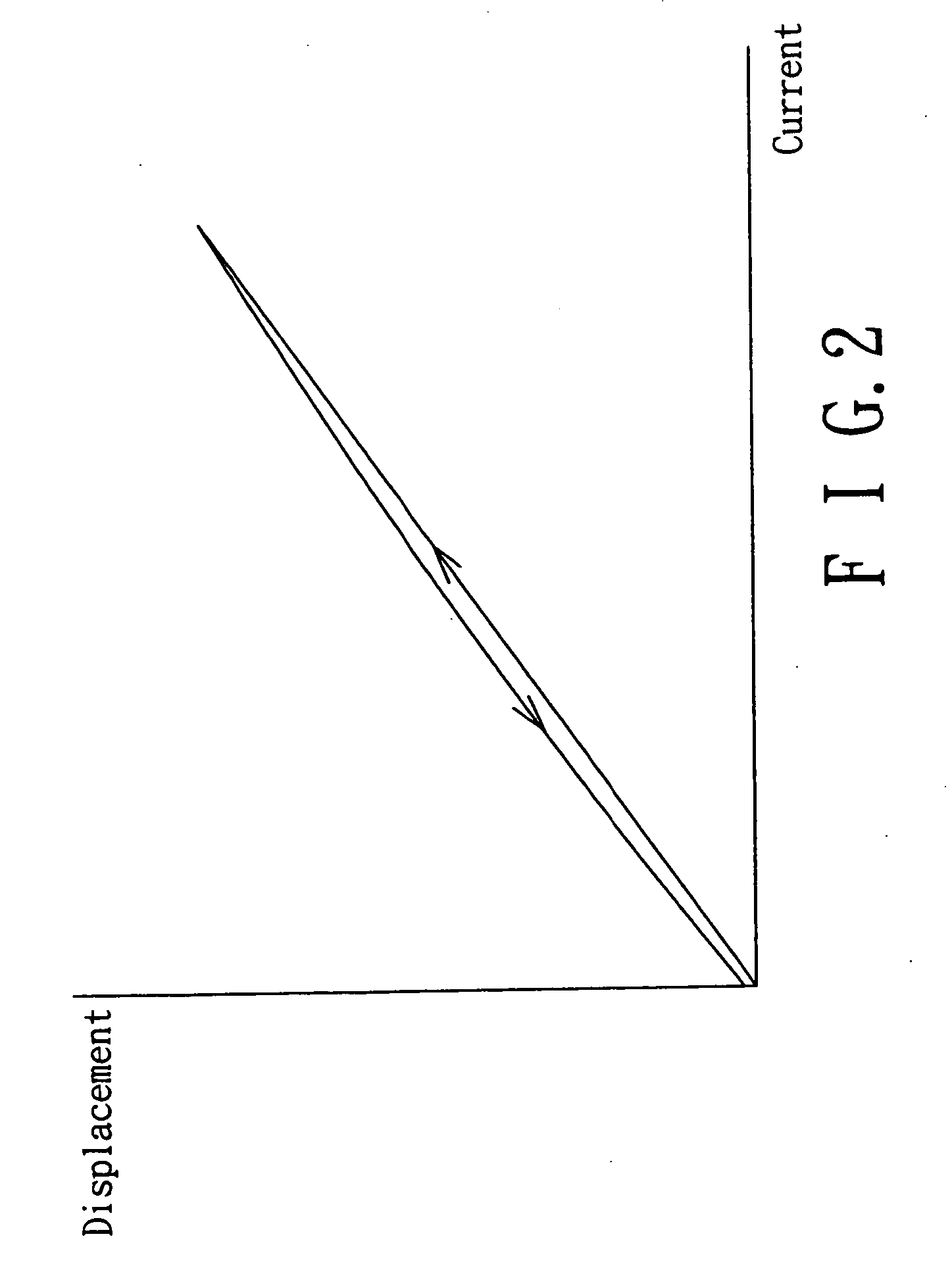
[0009] Another object of the present invention is to provide an auto-focusing method using voice coil motor for position feedback, which achieves precision positioning by obtaining the functional expression between voltage detected by the magnetic sensor and lens position and using it to provide feedback of lens position during auto focusing.
[0010] Yet another object of the present invention is to provide an auto-focusing device with voice coil motor for position feedback, which uses an electromagnetic actuator formed by two coils and two stacked permanent magnets with opposing poles to drive the lens to engage auto-focusing. Such design increases the magnetic flux density, enables full utilization of the effective magnetic field of permanent magnet, increases drive efficiency, and saves power consumption.

Problems solved by technology

Such design increases the magnetic flux density, enables full utilization of the effective magnetic field of permanent magnet, increases drive efficiency, and saves power consumption.

Method used


Image

  • Auto-focusing device with voice coil motor for position feedback and method for using same
  • Auto-focusing device with voice coil motor for position feedback and method for using same
  • Auto-focusing device with voice coil motor for position feedback and method for using same

Examples


Embodiment Construction

[0023]FIG. 3 shows the circuit diagram of a preferred embodiment of the auto-focusing device with voice coil motor for position feedback according to the invention. As shown, the auto-focusing device 20 comprises a lens barrel 31, a voice coil motor 22 (VCM), an image sensor 41, an image processing unit 24, a magnetic sensor 25, a position decoder 26, and a VCM driver 27.

[0024] The lens barrel 31 is an optical lens set consisting of a plurality of lenses, or in another preferred embodiment, a zooming lens set. The optical lens set and zooming lens set described are prior art and not one of the features of the invention. Thus their detailed constitution will not be elaborated below.

[0025] The voice coil motor 22 is attached to the lens barrel 31 and comprises coils and permanent magnets. It can electromagnetically drive the lens barrel 31 to engage in limited linear displacement, thereby adjusting the distance between lens barrel 31 and image sensor 41 to achieve the function of fo...


PUM


Abstract

An auto-focusing device with voice coil motor for position feedback comprises a lens holder, a sensor holder, a permanent magnet set, a yoke and a base. The lens holder holds a lens barrel and is wound around with at least two coils wound in opposite directions. The sensor holder holds an image sensor. The permanent magnet set includes at least two permanent magnets stacked together with opposing poles to form a multi-pole permanent magnet set. The permanent magnet set is furnished on the periphery of lens holder and corresponds to the two coils on lens holder. The permanent magnet set is disposed on the yoke to form a close-loop magnetism so as to increase the density of magnetic lines and the efficiency of magnetic force, save power consumption, and extend the service life of device.

Description

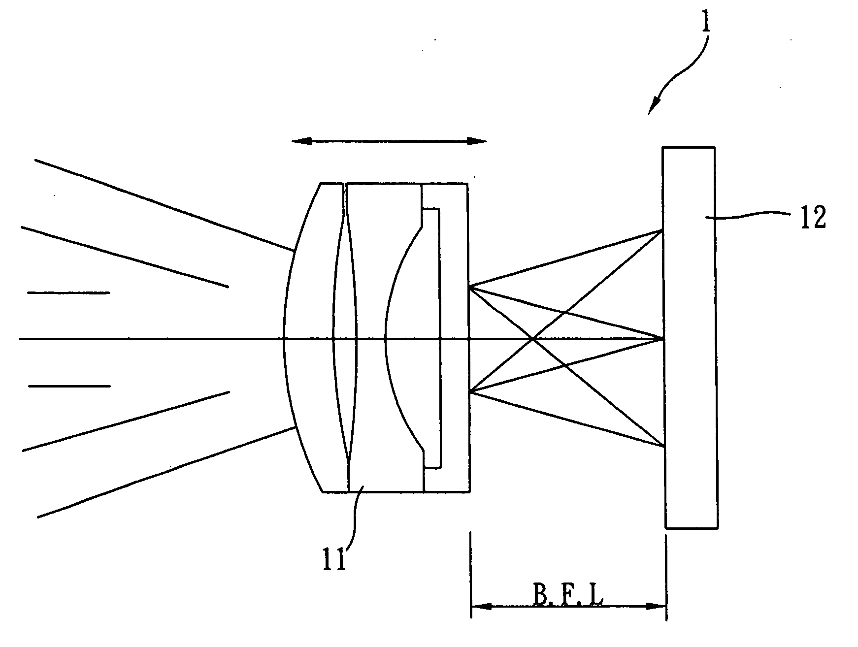
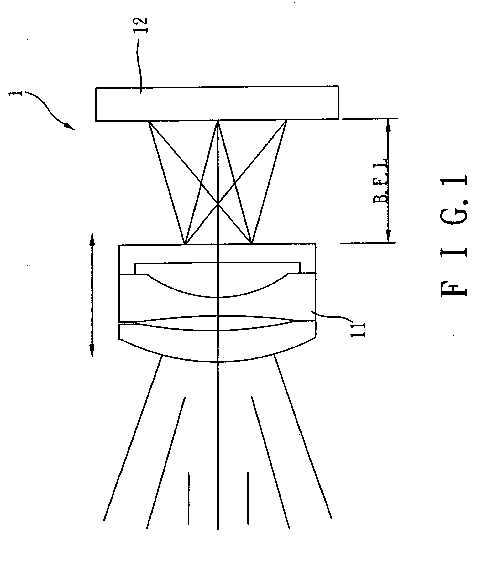
BACKGROUND OF INVENTION [0001] 1. Field of the Invention [0002] The present invention relates to an auto-focusing device with voice coil motor for position feedback, more particularly an auto-focusing device having a voice coil motor on its auto-focus lens as power source and a magnetic sensor to detect the position of lens for position feedback during auto-focus of lens. [0003] 2. Description of the Prior Art [0004] As shown in FIG. 1, a standard camera 1 comprises a lens set 11, an optical sensor 12 and a focusing mechanism (not shown in the figure). The lens set 11 forms an image on optical sensor 12 by refracting the light rays from an object. If the distance between lens set 11 and optical sensor 12 (back focal length, BFL) is fixed, the lens can only show clearly objects at its hyperfocal distance (e.g. 2-3 meters away). For the camera to shoot objects clearly at varying distances (for example at a close distance), the distance between lens set and sensor must be adjusted usin...

Claims


Application Information

Patent Timeline
Patent Type & Authority Applications(United States)
IPC IPC(8): G03B13/34
CPCG02B7/08H04N5/23212G03B3/02H04N23/55H04N23/67
Inventor CHANG, CHI LONEHSU, HUA CHENCHAO, PAUL C. P.
Owner POWERGATE OPTICAL INC
Learn More