Wind turbine and energy distribution system

a technology of wind turbines and energy distribution systems, applied in the direction of wind energy generation, wind motors with perpendicular air flow, liquid fuel engine components, etc., can solve the problems of increasing the complexity of the composite cross-section design of three-blade horizontal axis, the difficulty of integrating and connecting variable off-shore wind resources to existing shore-based power plants, and the limited frequency and access to the grid. achieve the effect of relieved growing energy demand, improved energy independence and the environmen

Inactive Publication Date: 2007-03-01
HARTMAN PAUL HARVEY
View PDF39 Cites 25 Cited by
  • Summary
  • Abstract
  • Description
  • Claims
  • Application Information

AI Technical Summary

Problems solved by technology

While many high value wind sites lie in mountain passes such as Tehachapi in California and Guadalupe in Texas they are limited in frequency and access to the grid.
The difficulties of the Nantucket Shoals project, general use of the shoreline as a recreational / tourist resource and valid ‘not in my back yard’ sentiments of the public demonstrate the limitations of this direction of development.
Another difficulty is integrating and connecting the variable off-shore wind resource to existing shore-based power plants that are the ties to the distribution grid.
As turbines get larger, the large moment of inertia in the three-blade horizontal axis design requires ever heavier composite cross-sections.
The strength to weight properties of composites will limit the turbine size in the same way the size of dinosaurs was limited by the properties of bone.
Production scale machines now so large that they need to be rotated whenever they pass below bridges.
Thinking in land based terms of ever larger turbines is not particularly useful within an ocean context where average wind energy can go from 500 W / m2 to 1000 W / m2 by moving slightly further off shore.
The top-heavy design of horizontal axis mills and transmission to shore increases the cost of off shore installations by a factor of at least three over comparable land installations.
Island installations have a more reasonable cost but are not scaleable in the sense that there are few opportunities available.
Placing large chemical production platforms off shore would seem to be more costly than placing them on land, and to invite the possibility of chemical spills in the aquatic environment.
Working with liquid Hydrogen is just barely handled safely by NASA at the present time.
In addition to the limitations described above, the fixed position of the platforms, the ungainly array of multiple horizontal axis wind turbines and the turbulence experienced in large storms present the challenge of catastrophic failure such as that of the Putnam 1.5 MW installation in Vermont during WW II.
The work has been focused on the use of oil shale and is quite far from producing a viable public power system.
Disadvantages of this approach were that heat could have produced directly from the fluid power and that the small scale of the installation could not effectively compete with utility based supply costs.
These efforts did not put forward a systems approach to supplying public energy needs.
Few designs have been put forward to collect off shore energy resources and deliver them by ship to shore based energy production and distribution infrastructure.
One early limitation was that it was not self-starting.
This process addresses a potential problem of conventional horizontal axis blades; mold form / lay up process can leave potential voids and hidden defects formed in the heavy wall polymerization process.
Wallace still uses conventional troposkein Darrieus geometry and has many of the limitations outlined for it.
Another limitation in the Darrieus design was the lack of pitch control.
Despite the advantages of vertical axis wind machines, they did not perform well in applications directly linked to the grid and are no longer produced in the US.

Method used


Image

  • Wind turbine and energy distribution system
  • Wind turbine and energy distribution system
  • Wind turbine and energy distribution system

Examples


Embodiment Construction

Wind Turbine and Heating Systems

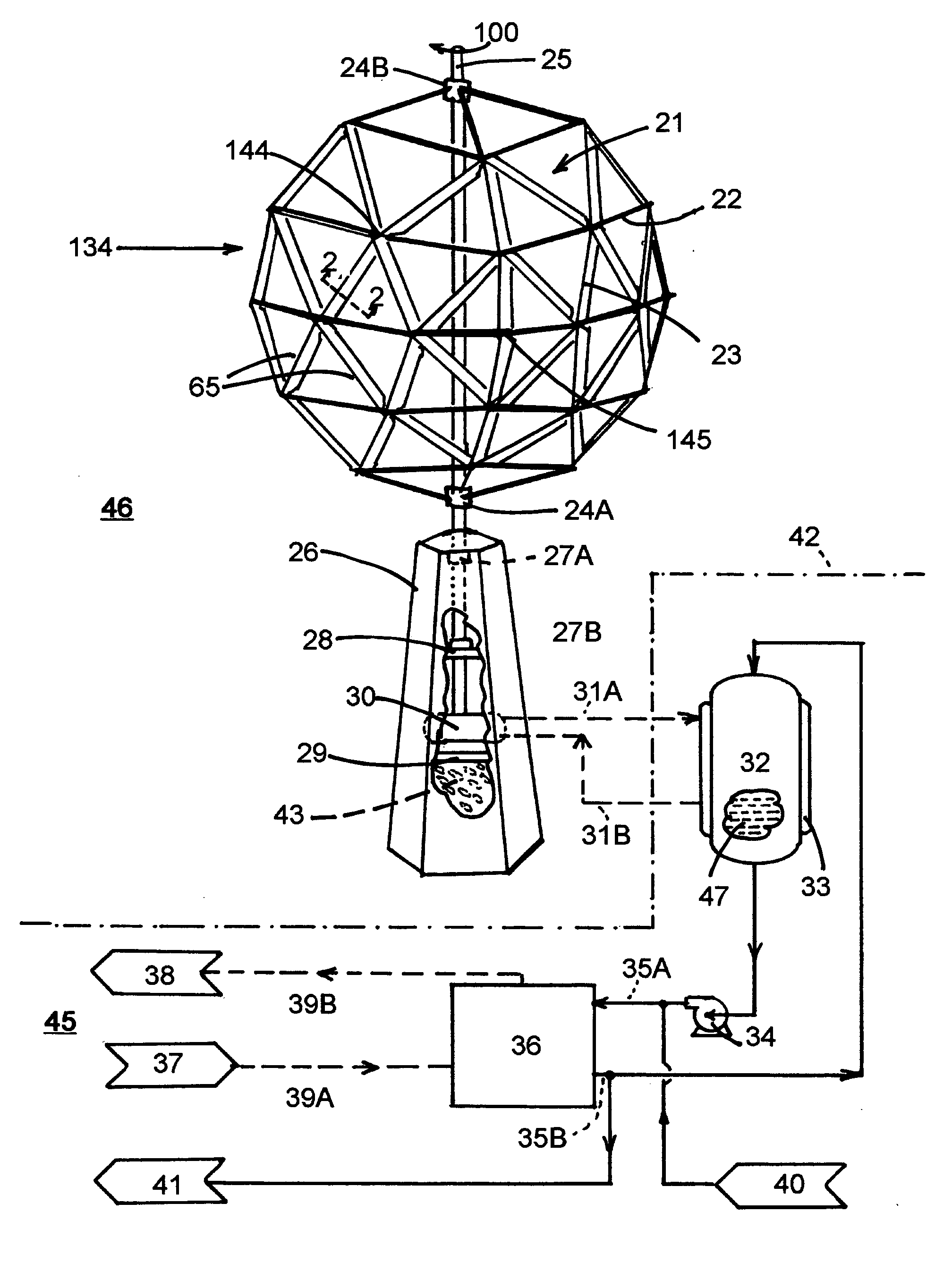
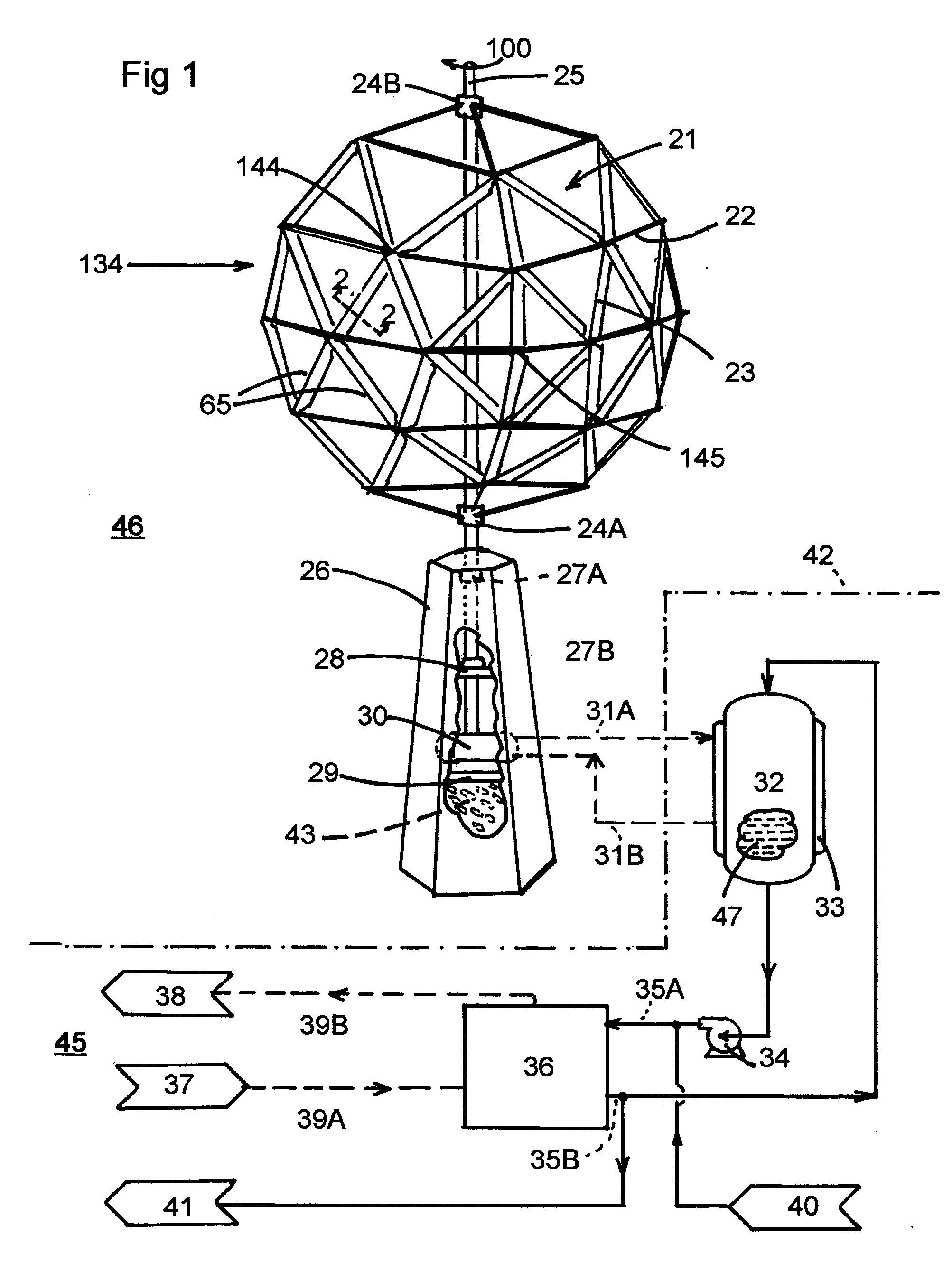
[0038] In the preferred embodiment of the invention, a wind energy resource 134 turns a novel vertical axis wind turbine 21 driving a thermal generator 30 to supply heat to a conventional heat pump system 45 for a commercial, industrial or agricultural building, (not shown). In areas of modest wind energy resources, an integrated wind heating system 46; allows for economical competition with the rising cost of natural gas, and the freeing of natural gas supply to uses such as electrical generation and transportation.

[0039] Turbine 21 is made up of a dome structure assembled from structural struts 22 and blade struts 23. (FIG. 1) The blade struts 23 all have leading edges 65 that are oriented in the same circumferential direction to reinforce rotation 100, (clockwise from above) of the turbine. The dome structure illustrated has octahedral symmetry with what is termed a three-frequency breakdown, (i.e.; each spherical segment is divided into three eq...


PUM


Abstract

A new design of vertical axis wind turbine is disclosed based on a dome structure using dome struts as blades that work in concert to produce rotational motion. The stability and low cost of the new design allows the turbine to function in low wind speed regimes as well as high speed winds that would be encountered in off-shore wind installations. The large stresses and structural requirements of mounting large horizontal axis wind turbines, particularly off-shore, are avoided with the new system. A new energy distribution system is proposed that will capture abundant off-shore wind energy, store it aboard a generator / delivery ship in the form of Hydrogen gas, and deliver it to an existing shore based power plant to produce electricity using a conventional gas turbine. Alternatively, the Hydrogen can be used to produce methane from coal using known processes to add natural gas to pipelines in areas that would normally be consuming the material. Both applications, and the direct production of heat by the new turbines, would stabilize our national energy grid while reducing CO2 emissions.

Description

BACKGROUND [0001] 1. Field of the Invention [0002] This invention relates to wind turbines and energy systems, specifically to vertical axis machines and systems that have the capability to supply public energy needs in combination with existing infrastructure and equipment. [0003] 2. Prior Art [0004] Large horizontal axis wind turbines have the lion's share of the current land based market. They also constitute the planning for off shore installations of very large (up to 5 MW) turbines. While many high value wind sites lie in mountain passes such as Tehachapi in California and Guadalupe in Texas they are limited in frequency and access to the grid. A host of attractive sites are found in the Great Plains, (called the ‘Saudi Arabia’ of wind), but lie a considerable distance from major population areas. [0005] Just off shore of major population centers on the Atlantic, Gulf Coast, Pacific and Great Lakes lie wind energy resources that dwarf on-shore wind energy available by factors ...

Claims


Application Information

Patent Timeline
Patent Type & Authority Applications(United States)
IPC IPC(8): B63H1/06
CPCB63H9/02B63J3/04F03D3/00F05B2240/931Y02T90/38Y02E10/721Y02E10/726Y02E10/74Y02T70/58Y02B10/30Y02E10/72Y02T70/5236Y02T90/40Y02P70/50
Inventor HARTMAN, PAUL
Owner HARTMAN PAUL HARVEY
Why Eureka
Try Eureka