Unlock instant, AI-driven research and patent intelligence for your innovation.
Anthracene derivative and hole transporting material, light emitting element, and electronic appliance using the same
Inactive Publication Date: 2007-03-01
SEMICON ENERGY LAB CO LTD
View PDF13 Cites 39 Cited by
Summary
Abstract
Description
Claims
Application Information
AI Technical Summary
This helps you quickly interpret patents by identifying the three key elements:
Problems solved by technology
Method used
Benefits of technology
Benefits of technology
[0006] Thus, it is an object of the present invention to provide a substance capable of contributing to obtaining a long lifetime light emitting element with a lower driving voltage.
[0020] In accordance with the present invention, an anthracene derivative that can be hardly crystallized, and can be superior in a carrier transporting property can be obtained. In addition, a light emitting element of the present invention having such a substance can achieve reduction of a driving voltage and a long lifetime. Further, by manufacturing a light emitting device with the use of the light emitting element, a highly reliable light emitting device with low power consumption and a long lifetime, and an electronic appliance incorporating the light emitting device can be provided.
Problems solved by technology
However, a light emitting element that is formed using a conventional diphenylanthracene derivative has a high driving voltage.
Therefore, the light emitting element can not be fulfilled a requirement of being driven with a low voltage in order to realize low power consumption and downsizing of power supply.
Method used
Image
Click on the blue label to locate the original text in one second.
Reading with bidirectional positioning of images and text.
Examples
embodiment mode 1
[0038] One mode of the present invention is an anthracene derivative represented by structural formulas (4) to (24).
[0039] Since the anthracene derivatives of the present invention described above have a high volume structure, crystallization and dimerization of an anthracene skeleton can be suppressed. Further, the anthracene derivative of the present invention has a superior carrier transporting property.
embodiment mode 2
[0040] A synthesis method of an anthracene derivative represented by a general formula (25) of the present invention will be explained below. It is to be noted that an anthracene derivative of the present invention is not limited to a synthesis method described in this embodiment mode, and the anthracene derivative may be synthesized by another synthesis method.
[0041] In the general formula (25), each of R1 to R8 represents hydrogen or an alkyl group having 1 to 4 carbon atoms. Further, R represents the above general formula (26) or (27). Each of R9 to R22 represents hydrogen, an alkyl group having 1 to 4 carbon atoms, or a substituted or unsubstituted aryl group.
[0042] As shown in a synthesis scheme (a-1), a halogen compound such as bromide or iodide having the general formula (26) or (27) and alkyllithium are reacted with each other. Then, an obtained compound and a compound having an anthraquinone skeleton are reacted with each other, and water is added thereto, whereby a diol...
embodiment mode 3
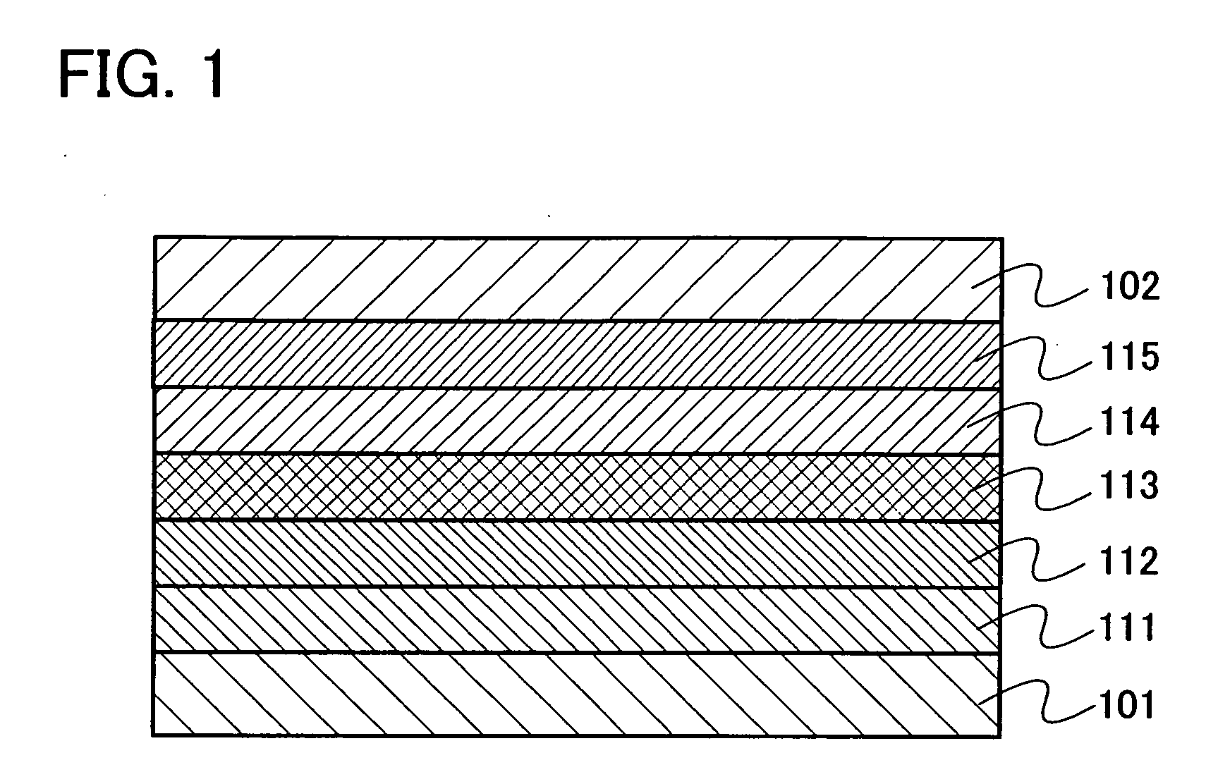
[0045] A mode of a light emitting element using an anthracene derivative of the present invention as a hole transporting material will be explained with reference to FIG. 1.
[0046] In FIG. 1, in addition to a light emitting layer 113, a hole injecting layer 111, a hole transporting layer 112, an electron transporting layer 114, an electron injecting layer 115, and the like are provided between a first electrode 101 and a second electrode 102. These layers are stacked so that holes are injected from a first electrode 101 side and electrons are injected form a second electrode 102 side, when a voltage is applied so that potential of the first electrode 101 is higher than that of the second electrode 102.
[0047] In such a light emitting element, holes injected from the first electrode 101 side and electrons injected form the second electrode 102 side are recombined in the light emitting element 113 to make a light emitting substance be an excited state. Then, when the light emitting su...
PUM
Property
Measurement
Unit
Electric potential / voltage
aaaaa
aaaaa
Abstract
It is an object of the present invention to provide a substance capable of contributing to obtaining a light emitting element with a low driving voltage and long lifetime. An anthracene derivative represented by a general formula (1) is provided. In the general formula (1), each of R1 to R8 represents hydrogen or an alkyl group having 1 to 4 carbon atoms. Further, each of R9 to R17 represents hydrogen, an alkyl group having 1 to 4 carbon atoms, or a substituted or unsubstituted aryl group. Such an anthracene derivative can be hardly crystallized, and can be superior in a carrier transporting property. Therefore, by using the anthracene derivative, a light emitting element with a low driving voltage and long lifetime can be manufactured.
Description
TECHNICAL FIELD [0001] The present invention relates to a substance that can be used as a material for manufacturing a light emitting element. BACKGROUND ART [0002] In recent years, many light emitting elements utilized for a display and the like have a structure in which a layer including a light-emitting substance is sandwiched between a pair of electrodes. In such a light emitting element, electrons injected from one of the electrodes and holes injected from the other electrode are recombined to form excitons. Then, when the excitons return to a ground state, the light emitting element emits light. [0003] In a field of a light emitting element, in order to obtain light emitting element having high luminous efficiency and a long lifetime with little deterioration, a substance to be a material for manufacturing an element has been researched in various ways. [0004] Incidentally, as one of causes for deterioration of a light emitting element, crystallization of a substance forming a...
Claims
Application Information
Patent Timeline
Application Date:The date an application was filed.
Publication Date:The date a patent or application was officially published.
First Publication Date:The earliest publication date of a patent with the same application number.
Issue Date:Publication date of the patent grant document.
PCT Entry Date:The Entry date of PCT National Phase.
Estimated Expiry Date:The statutory expiry date of a patent right according to the Patent Law, and it is the longest term of protection that the patent right can achieve without the termination of the patent right due to other reasons(Term extension factor has been taken into account ).
Invalid Date:Actual expiry date is based on effective date or publication date of legal transaction data of invalid patent.

