
Streaming video network system

Active Publication Date: 2007-03-01
GYRUS ACMI INC (D B A OLYMPUS SURGICAL TECH AMERICA)
View PDF30 Cites 89 Cited by
  • Summary
  • Abstract
  • Description
  • Claims
  • Application Information

AI Technical Summary

Benefits of technology

[0020] It is an objective of the invention to improve operating room, staff and surgeon efficiency by providing live remote access to video which originates in hospital operating rooms and clinics. It is a further object of the present invention to increase the level of control that users can leverage over the video sources at the originating location. It is an added object of the invention to increase the potential audience and number of locations from which live-video can be accessed, such as operating rooms, offices, conference rooms and video walls to name a few. It is also an object of the current invention to offer an adequate level of auditing and security controls to assist hospitals in their need to be HIPAA compliant.
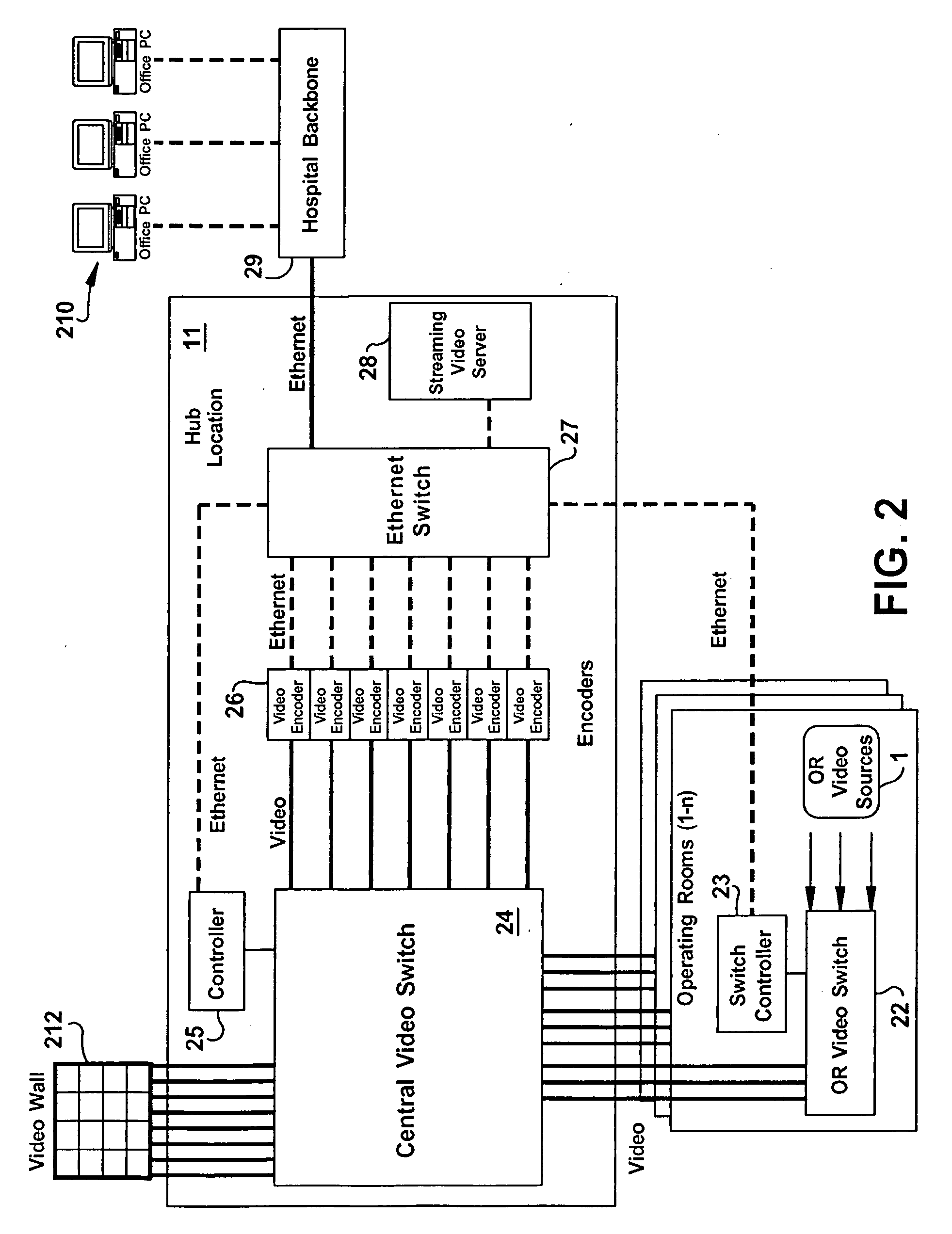
[0027] Another aspect of the invention allows for the use of streaming video decoder devices, which are capable of receiving digital video streams and converting them to the original analog video or displayable digital signal format. Current art integrated operating systems typically utilize analog video switching systems, and therefore, these decoder devices are required to allow virtual video circuit connections to be established between operating rooms, or between operating rooms and conference rooms (as examples). The system allows for the creation of digital connections, but is dependent on available technology and operating room capabilities. The system architecture is flexible and will accommodate both analog and digital devices. Using analog and digital streaming video decoder technology within this aspect of the invention allows for the creation of a video wall, which can be used to simultaneously monitor all operating room locations.
[0028] A further aspect of the invention enables the transmission of pathology images onto the digital streaming network. Pathology images can be received and viewed at any of the locations serviced by the digital streaming network. Most importantly, pathology images can be viewed from within an operating room, saving valuable time that would be required to walk to and from pathology, and avoiding the sterility problem of surgeons having to exit and re-enter the sterile field.

Problems solved by technology

Students and additional staff do not need to be present in the operating room, causing crowding, and potential distractions for the surgeon.
Although the video quality of analog systems is generally adequate for current art cameras, this approach has several key limitations: The number of users served by this solution is limited, because hard-wired video signals must be brought to each ‘user’ The number of locations that can be served by this solution is equally so limited.
Wide-scale deployment of this solution is severely limited in all but new construction, due to the extensive cable infrastructure that must be installed.
Distance limitations exist for video that must be addressed by expensive fiber-optic transmission equipment.
Usage and viewing of this video is extremely difficult, if not impossible to track.
The solution is not easily scalable to add more locations or more sources at a given location.
The cost of installing and maintaining the dedicated video cable infrastructure is high.
It is also important to note that the ability to remotely view a single video source of video from inside the operating room is generally inadequate.

Method used


Image

  • Streaming video network system
  • Streaming video network system
  • Streaming video network system

Examples


Embodiment Construction

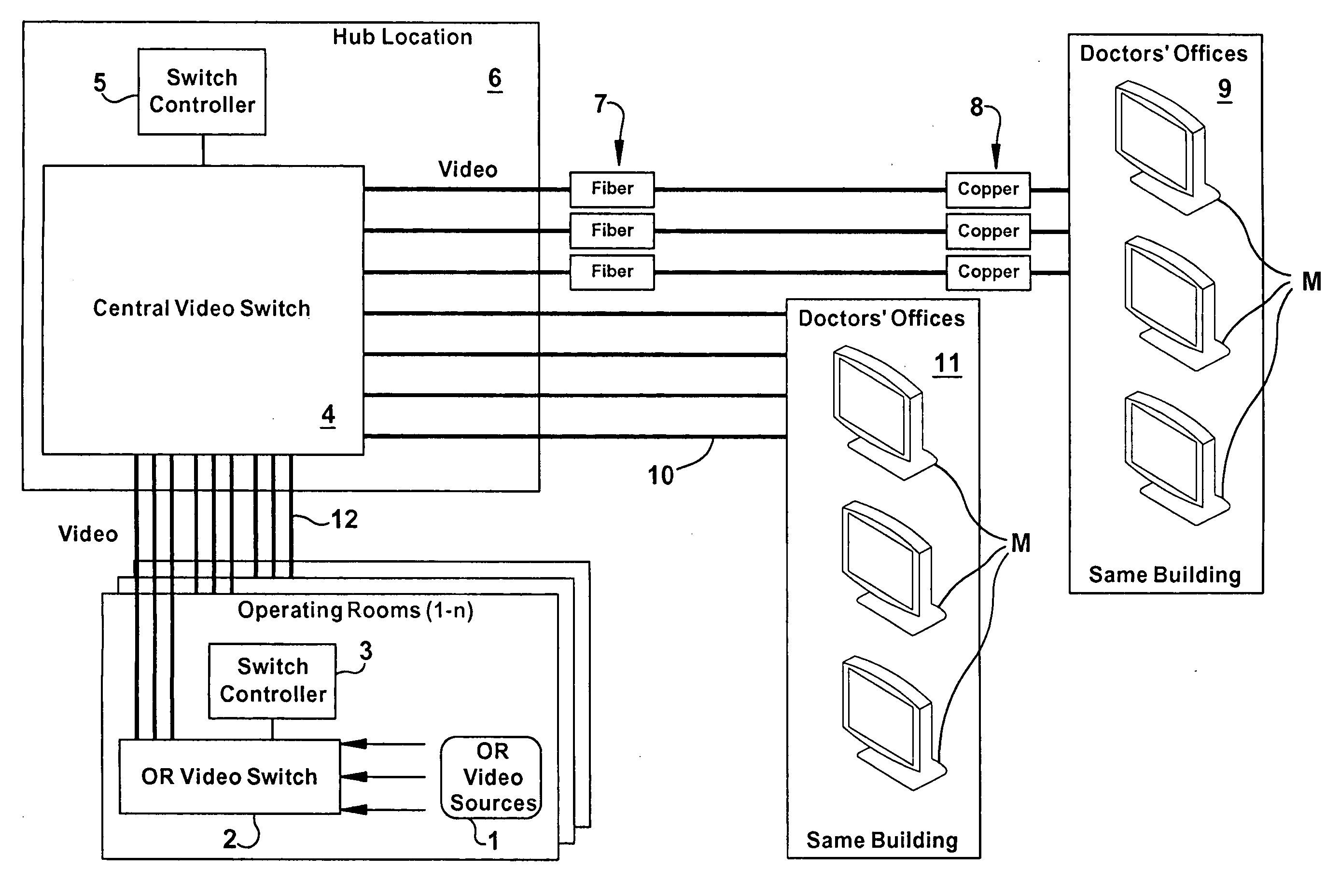
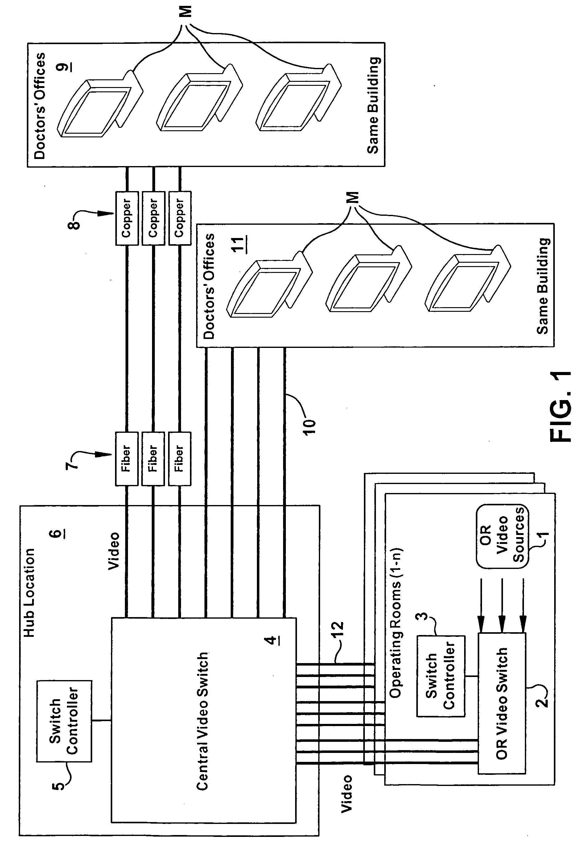
[0040]FIG. 1 is a schematic diagram of an analog video distribution system (hub) which enables OR to OR and Limited OR to Office visualization. Operating room video sources (1) may be connected to a video switch (2) located in or near the operating room. The video switch is controlled by a video switch controller (3). Video may alternatively be connected directly to the outbound video links 12, which are typically coaxial video cable linked back to a central hub location (6), and connected to a central video switch (4). The central video switch is controlled by a video switch controller (5). Video cabling, again typically coaxial cable (10), is run from the hub location (6) to viewing locations such as doctor's offices in the same building (11). For longer distances, fiber / copper transceivers (7, 8) are required, along with fiber infrastructure, in order for users in other buildings to view OR video. Dedicated monitors M at the remote viewing locations are used to visualize the vide...


PUM


Abstract

A distributed, digital, network-based, streaming video solution allows users to view live streaming digital video from multiple video sources in multiple operating rooms at any location connected to a network. One or more video sources in an operating room are connected to a streaming video encoder capable of converting the video to a network packet stream. Once the digital video stream is available on the network, it may be accessed and routed through the use of a streaming video control server. The streaming video control server is responsible for user authentication and authorization and web page access for remote viewing and video source selection by users. The control server also provides audit logging services, operating room selection and overall system resource allocation. The video control server also provides a network-based remote control interface, which enables other systems to communicate on the streaming video network, and allows for remote control of visualization from an integrated operating room control system, and provides the ability for one operating room to look into other operating rooms.

Description

RELATED APPLICATION [0001] This application is related to provisional application No. 60 / 740,886, filed on Aug. 24, 2005.FIELD OF THE INVENTION [0002] The invention relates generally to the streaming of digital video and audio over data networks, where the source originates from medical clinical or surgical procedures, where remote visualization is required from other locations, such as operating rooms, offices or conference rooms, where remote selection and control of video sources may be required, and where HIPAA compliance enabling features are needed. BACKGROUND OF THE INVENTION [0003] With the development and practice of Minimally Invasive Surgical (MIS) technique, has come a proliferation of medical and non-medical devices that generate video in the hospital operating room and in medical clinics. The term MIS is used to describe a number of surgeries as well as diagnostic procedures. MIS includes both laparoscopy (surgery through small holes) and endoscopy (diagnostic and ther...

Claims


Application Information

Patent Timeline
IPC IPC(8): H04N7/16H04N7/173
CPCH04N7/141A61B5/0013H04N21/25891H04N21/4363H04N21/266H04N7/163H04N21/441H04N21/4122H04N21/25875H04N7/15H04N21/2143H04N21/43632H04N21/647H04N21/4223H04N7/17318H04N7/181H04N21/44222H04N21/47202H04N21/44224
Inventor RENZI, PETERMITCHELL, EDDIE
Owner GYRUS ACMI INC (D B A OLYMPUS SURGICAL TECH AMERICA)
Learn More