
Naphthalene compound with terminal hydrogen, liquid crystal composition including the compound, and LCD device including the liquid crystal composition

a terminal hydrogen and naphthalene technology, applied in the field of naphthalene compound with terminal hydrogen, liquid crystal display device including liquid crystal composition, can solve the problems of difficult reverse domain formation, short response time, and large development of lc compounds, and achieve excellent properties, reduce the driving voltage of the lcd device, and improve the effect of lcd performan

Inactive Publication Date: 2007-03-08
JNC CORP +1
View PDF2 Cites 13 Cited by
  • Summary
  • Abstract
  • Description
  • Claims
  • Application Information

AI Technical Summary

Benefits of technology

[0043] The LC compound of this invention is positively large in the dielectric anisotropy and the optical anisotropy, and is also excellent in the properties generally required for an LC composition. The LC composition including the LC compound has the properties generally required for an LC composition, and is large in the dielectric anisotropy and the optical anisotropy. Such an LC composition is particularly useful in lowering the driving voltage of the LCD device, and is also particularly useful to an LCD device having a small cell gap for high-speed response.
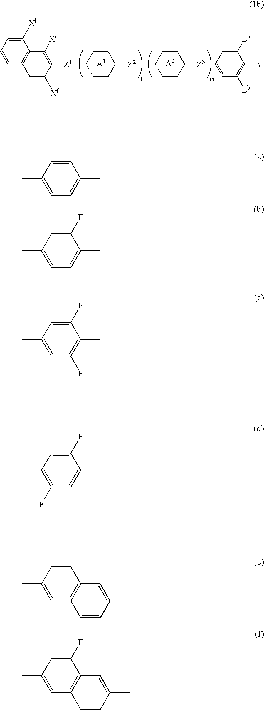
[0044] The terminology used is this specification is described as follows. The term “liquid crystal compound” is a general term for a compound having a LC phase like nematic phase or smectic phase, and so forth, and for a compound having no LC phase but is useful as a component of LC composition. An LC compound, an LC composition and an LCD device are often simply called a compound, a composition and a device, respectively. The term “LCD device” is the general term for a LCD panel and a LCD module. The upper-limit temperature of a nematic phase is the phase transition temperature from the nematic phase to an isotropic phase, sometimes simply called an upper-limit temperature, while the lower-limit temperature of a nematic phase is sometimes simply called a lower-limit temperature. The compounds respectively expressed by formulae (1a), (1b), (1c-1), (1c-2) and (1c-3) are often simply called compounds (1a), (1b), (1c-1), (1c-2) and (1c-3), respectively. This abbreviation rule is also applied to the compounds respectively expressed by formulae (1c-1-1) to (1c-1-4), formulae (1c-2-1) to (1c-2-12) and formula (2). Moreover, the compounds (1a), (1b), (1c-1) to (1c-3), (1c-1-1) to (1c-1-4) and (1c-2-1) to (1c-2-12) are generally called compounds (1). In formulae (2) to (14), the hexagonal symbols with B, D, E and so forth respectively enclosed therein correspond to rings B, D, E and so forth, respectively. The amount of a compound expressed with “%” means the percentage by weight based on the total weight of th...

Problems solved by technology

However, since controlling the elastic constant of an LC composition is difficult, LC compositions with large dielectric anisotropy are usually used, thus causing great development of LC compounds with large dielectric anisotropy.
When the cell gap of a TN-mode device is small, the response time is short and a reverse domain is difficult to form.
When the cell gap of an OCB-mode device is small, the transfer time from splay alignment to bend alignment becomes short, and the response time, i.e., the time needed for the alignment of the LC molecules to change in response to the change of the applied voltage, is also short.

Method used


Image

  • Naphthalene compound with terminal hydrogen, liquid crystal composition including the compound, and LCD device including the liquid crystal composition
  • Naphthalene compound with terminal hydrogen, liquid crystal composition including the compound, and LCD device including the liquid crystal composition
  • Naphthalene compound with terminal hydrogen, liquid crystal composition including the compound, and LCD device including the liquid crystal composition

Examples


example 1

Synthesis of 2-(4′-chloro-2,3′-difluorobiphenyl-4-yl)naphthalene (No. 53)

[0118] Step 1:

[0119] A mixture of 10.00 g (=47.33 mmol) of 2-bromonaphthalene, 7.95 g (=56.82 mmol) of 3-fluorophenylboric acid, 9.81 g (=70.98 mmol) of K2CO3, 3.81 g (=11.82 mmol) of tetrabutylammonium bromide, 1.00 g (=1.42 mmol) of dichlorobis(triphenylphosphine) palladium(II), 0.76 g (=2.84 mmol) of triphenylphosphine and a 100 ml mixed solvent of toluene / water / ethanol in a ratio of 1:1:1 was stirred for 7 hours with reflux. The reaction mixture obtained was extracted twice with toluene. The extract was washed thrice with water and then dried with anhydrous MgSO4. After the solvent was evaporated under a reduced pressure, the obtained black solid of 15.40 g was purified with silica gel chromatography using heptane / toluene in a ratio of 5:1 as the eluent, thereby obtaining a white solid of 10.98 g. The white solid was recrystallized with a mixed solvent of Solumix / heptane in a ratio of 1:1 to obtain 8.90 ...

example 2

Synthesis of 2-[2-(2,4′-difluorobiphenyl-4-yl)ethyl]naphthalene (No. 103)

[0124] Step 1:

[0125] In the step, 35.00 g (77.55 mmol) of (3-fluorobenzyl)triphenylphosphonium bromide was suspended in 150 ml of THF, and the suspension was cooled to −30° C. and added with 10.25 g (=88.61 mmols) of potassium t-butoxide under stirring. After the addition was finished, the reaction solution was stirred at the same temperature for 1 hour, a 50 ml THF solution of 8.65 g (=55.38 mmol) of 2-naphthoaldehyde was dropped into the same, and then the mixture was slowly heated to room temperature. After being stirred for 18 hours, the reaction mixture was added into iced water, and the mixture was extracted thrice with toluene. The extract was washed thrice with water and then dried with anhydrous MgSO4. After the solvent was evaporated under a reduced pressure, the obtained yellow solid of 43.34 g was purified with silica gel chromatography using heptane as the eluent to obtain 11.54 g of 2-[2-(3-flu...

example 3

Synthesis of 2-{3-fluoro-4-[2-(4-fluorophenyl)ethyl]phenyl}naphthalene (No. 145)

[0132] Step 1:

[0133] A 86.86 ml cyclohexane solution of sec-butyl lithium in a concentration of 1.01M was dropped into a 300 ml THF solution of 15.00 g (=67.49 mmol) of 2-(3-fluorophenyl)naphthalene at −70° C. After the dropping was finished, the reaction solution was stirred at the same temperature for 1 hour, added with a 150 ml THF solution of 10.88 g (=94.49 mmol) of 4-formylmorpholine through dropping and then slowly heated to room temperature. After being stirred for 18 hours, 25 ml of 6N HCl(aq) was dropped into the reaction solution, and then the reaction mixture was extracted thrice with toluene. The extract was washed with water and an aqueous solution of NaHCO3, and then dried with anhydrous MgSO4. After the solvent was evaporated under a reduced pressure, the obtained yellow solid of 16.83 g was purified with silica gel chromatography using toluene as the eluent to obtain a yellowish solid...


PUM

PropertyMeasurementUnit
Fractionaaaaaaaaaa
Fractionaaaaaaaaaa
Fractionaaaaaaaaaa

Abstract

A liquid crystal (LC) compound having generally required physical properties, low viscosity, proper optical anisotropy, proper dielectric anisotropy and good compatibility with other LC compounds is described. An LC composition including the compound and an LCD device including the composition are also described. The compound is expressed by formula (1a): wherein the ring A1 and the ring A2 are independently 1,4-phenylene, pyridine-2,5-diyl, pyrimidine-2,5-diyl or naphthalene-2,6-diyl, in which any hydrogen can be replaced by halogen; Z1, Z2 and Z3 are independently a single bond, —(CH2 )2—, —(CH2 )4—, —CH═CH—, —C≡C—, —CF2O—, —OCF2—, —COO— or —OCO—; Xa, Xb, Xc, Xd, Xe and Xf are independently hydrogen or fluorine; Y is —OCH2F, —OCHF2, —OCF3, —SCH2F, —SCHF2, —SCF3, —CH2F, —CHF2, —CF3, fluorine or chlorine; La and Lb are independently hydrogen or fluorine; and “l” and “m” are independently equal to 0 or 1.

Description

CROSS-REFERENCE TO RELATED APPLICATION [0001] This application claims the priority benefit of Japan application serial no. 2005-260157, filed on Sep. 8, 2005. All disclosure of the Japan application is incorporated herein by reference. BACKGROUND OF THIS INVENTION [0002] 1. Field of this Invention [0003] This invention relates to a liquid crystal (LC) compound, an LC composition and a liquid crystal display (LCD) device, and more particularly relates to a naphthalene compound with a terminal hydrogen atom, an LC composition including the compound and an LCD device including the liquid crystal composition. [0004] 2. Description of the Related Art [0005] In a LCD device, classification based on an operating mode of LCs includes phase change (PC), twisted nematic (TN), in-plane switching (IPS), super twisted nematic (STN), optically compensated bend (OCB), electrically controlled birefringence (ECB), vertical alignment (VA) and so forth. Classification based on a driving mode includes ...

Claims


Application Information

Patent Timeline
IPC IPC(8): C07D403/02C09K19/02C07D401/02C09K19/34C09K19/32
CPCC09K19/322
Inventor KONDOU, TOMOYUKIMATSUI, SHUICHIKIMURA, KEIJI
Owner JNC CORP
Learn More