Flow through cell for optical spectroscopy

a flow through cell and optical spectroscopy technology, applied in the direction of components, instruments, withdrawing sample devices, etc., can solve the problems of difficult manufacturing of through cells, and achieve the effect of convenient manufacturing, convenient clamping together, and convenient manufactur

Active Publication Date: 2007-03-08
AGILENT TECH AUSTRALIA M
View PDF17 Cites 12 Cited by
  • Summary
  • Abstract
  • Description
  • Claims
  • Application Information

AI Technical Summary

Benefits of technology

[0015] Formation of the flow through cell from a plurality of body members, which may be formed from a corrosion-resistant metal such as for example titanium, or from an appropriate engineering plastic such as for example polyether ether ketone, offers several advantages in that appropriately shaped body members can be readily manufactured by machining or moulding. The body members are not of complex shapes being generally of rectangular parallelepiped shape, and are readily clampable together, for example by machine screws or by through bolts with nuts, or by external clamps. The optically transparent windows can be provided by inserting windows of suitable materials into the body members and appropriately sealing them against the high pressure fluid flow through the flow through passage. An example sealing structure is taught by H. T. Magnussen, Jr. in U.S. Pat. No. 5,062,706 (Nov. 5, 1991), however persons skilled in the art will know of other suitable sealing methods. Alternatively, as described above, plates of transparent material can be sandwiched between resilient gaskets and body members to provide windows. The use of resilient gaskets provides for sealing against leakage of flowing liquid, and is particularly advantageous for readily manufacturing a flow through cell to withstand high pressure liquid flows. Thus the invention provides a flow through cell for spectrophotometry that is relatively easi

Problems solved by technology

However both of these flow through

Method used


Image

  • Flow through cell for optical spectroscopy
  • Flow through cell for optical spectroscopy
  • Flow through cell for optical spectroscopy

Examples


Embodiment Construction

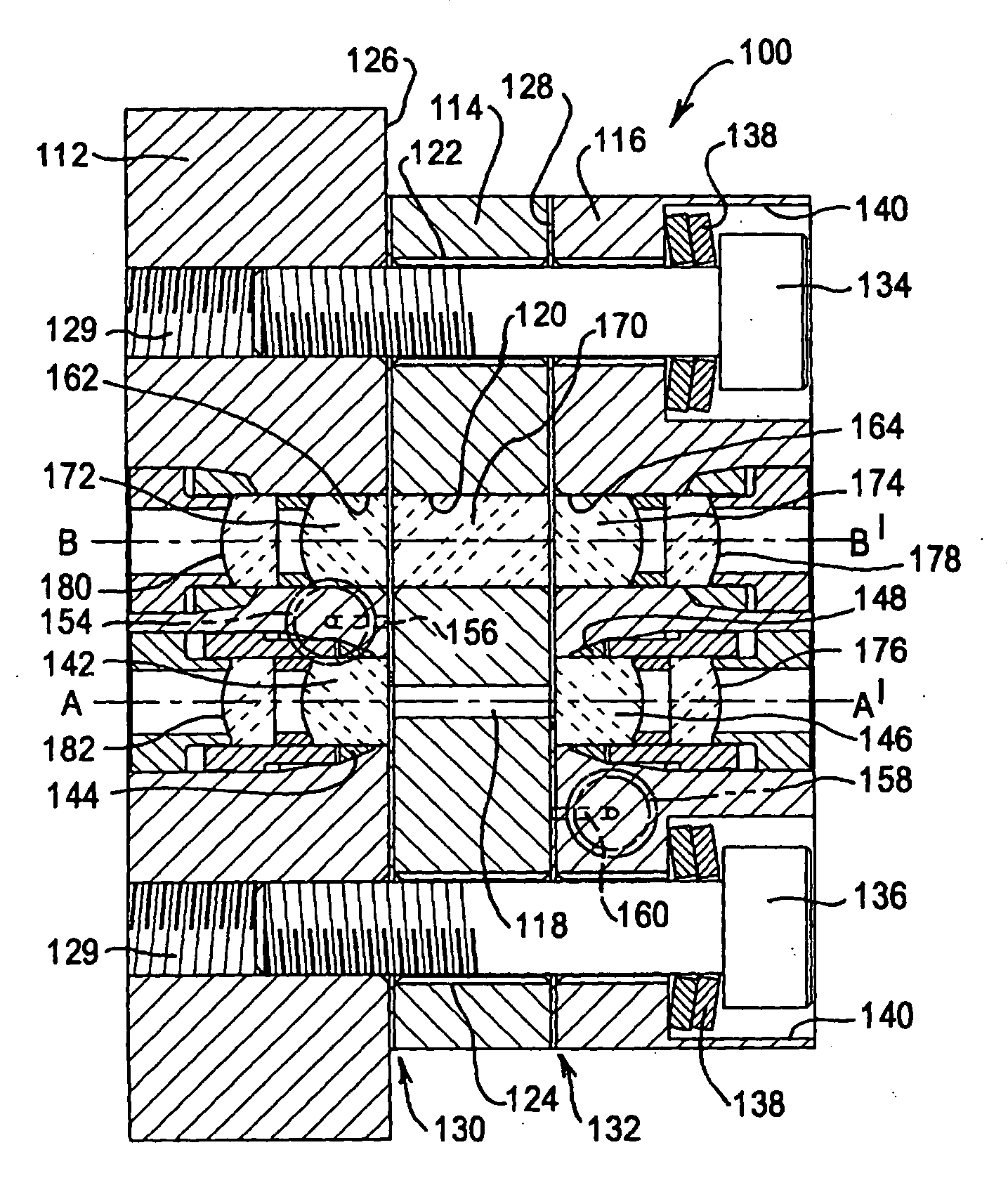
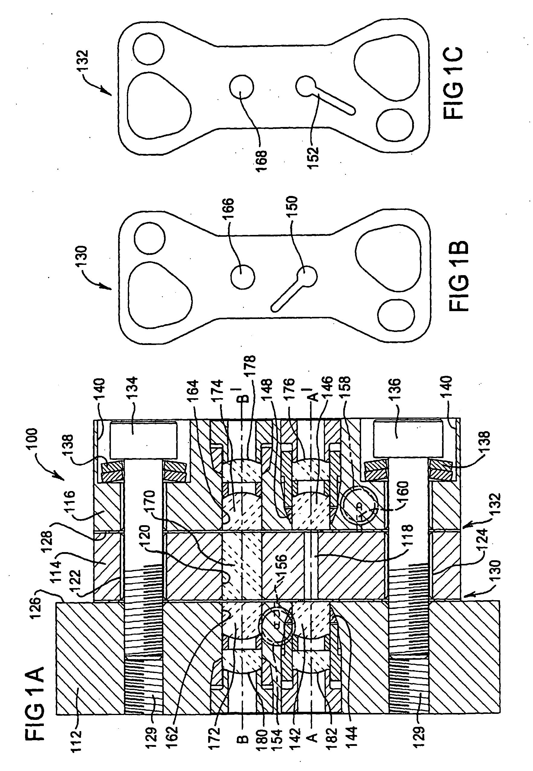
[0031] Referring first to FIG. 1A, the illustrated flow through cell 100 is constructed from three body members 112, 114, and 116. Body member 114 is an intermediate body member located between body members 112 and 116. It has two parallel flat faces and includes four holes 118, 120, 122 and 124 extending therethrough perpendicularly from one face thereof. Body members 112 and 116 are provided with parallel flat faces 126 and 128 respectively. Body members 112 and 116 include through holes which align with holes 122 and 124 through intermediate body member 114 for assembling the flow through cell as will be described below. The holes through body member 112 may be threaded as indicated by reference 129. To form cell 100 a gasket 130 (see FIG. 1B) made for example from a tetrafluoroethylene hexafluoropropylene copolymer (‘FEP’, E. I. du Pont de Nemours and Company) is placed against flat face 126 of body member 112, body member 114 is placed against gasket 130, a gasket 132 (see FIG....


PUM


Abstract

A flow through cell (100) for use in a spectrophotometer for analysis of dissolved chemical substances in a flowing liquid stream is made up of at least an intermediate body member (114) located between two other body members (112, 116). The body members are of regular shape, for example rectangular parallelepiped and are clamped together, for example by machine screws (134, 136). Thus the cell is relatively easily manufacturable. The clamped together body members define a flow through passage which includes a hole (118) through the intermediate body member (114) and a liquid inlet region at one end of the hole and a liquid outlet region at the other end of the hole, which regions may be provided by galleries (150, 152) in scaling gaskets (130, 132) between the body members. The two other body members each include an optically transparent window (142, 146) at an end of the hole (118) thereby providing an optical pathway (A, A′) through part of the flow through passage. The liquid inlet and outlet regions at the ends of hole (118) are such that the liquid flow on entering and leaving the optical pathway (A, A′) occurs adjacent the optical windows transversely of the flow along the optical pathway. Thus the liquid flow sweeps across the optical windows (142, 146) and flushes the hole (118) of the optical pathway by successive increments of the liquid with minimal mixing.

Description

TECHNICAL FIELD [0001] The present invention relates to a flow through cell for use in a spectrophotometer for analysis of dissolved substances in a flowing liquid stream. The invention is particularly useful with high performance liquid chromatography. BACKGROUND [0002] The following discussion of the background to the invention is included to explain the context of the invention. This is not to be taken as an admission that any of the material referred to was published, known or part of the common general knowledge in Australia as at the priority date established by the present application. [0003] It is frequently useful to detect and to determine the concentrations of various dissolved chemical substances present in varying concentrations in a flowing liquid stream such as, for example, the effluent of a high-performance liquid chromatograph. If such chemical substances absorb light of characteristic wavelengths they can be detected by spectrophotometry. It is convenient to pass ...

Claims


Application Information

Patent Timeline
IPC IPC(8): G01N1/10G01N21/05G01N30/74
CPCG01N21/05G01N2021/0346G01N30/74
Inventor BLAIR, ROBERT W.
Owner AGILENT TECH AUSTRALIA M
Why Eureka
Try Eureka