
Method of thermal spraying

Inactive Publication Date: 2007-03-08
KYUSHU ELECTRIC POWER CO INC +1
View PDF7 Cites 12 Cited by
  • Summary
  • Abstract
  • Description
  • Claims
  • Application Information

AI Technical Summary

Benefits of technology

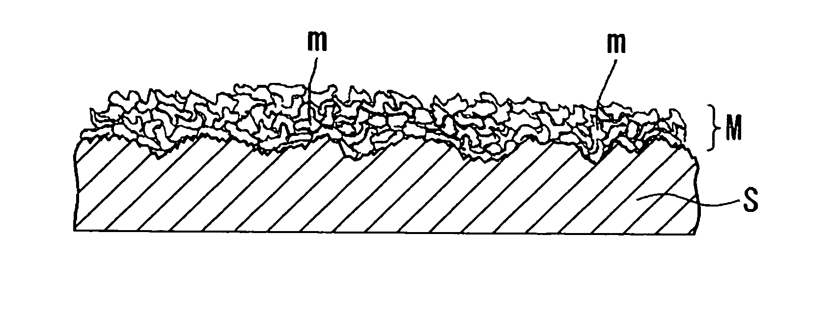
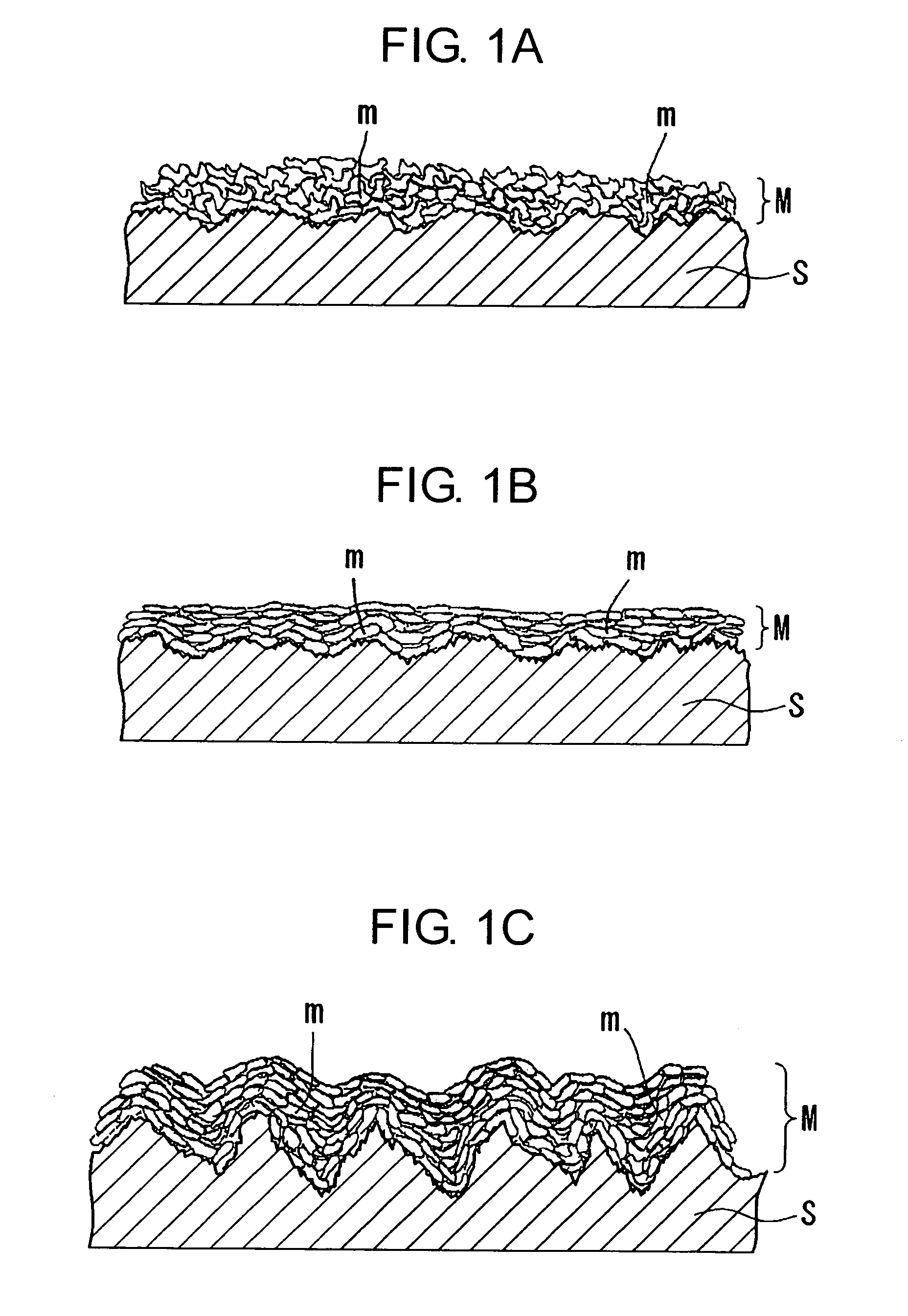
[0019] When plasma spraying is performed under the condition in which the average area of each molten particle when the molten particles have stuck to the surface of the thermal spraying subject falls within a predetermined range, a temperature of the surface of the thermal spraying subject increases and wettability of a droplet with respect to the surface of the thermal spraying subject is improved. Thus, even if roughening is performed by the grinding tool that provides a lower level of roughness than the blast treatment, the adhesion strength of the spray coating that is considerable to that obtained by a combination of the blast treatment and gas flame spraying can be obtained. In the roughening by means of the grinding tool, a large-scale apparatus is not needed as different from the blast treatment, a portable small tool can be used in overhead location work at field repair, and scattering powder resulting from the roughening is slight so that a danger of environmental pollution is low. Furthermore, if thermal spraying can be performed under the condition in which the average area of each molten particle is 10000 to 100000 μm2 by using arc spraying in place of plasma spraying, the same operations and advantages as those described above can be obtained.

Problems solved by technology

The coating has problems that a coating cost is expensive, a useful life is limited, and a repair cost is also expensive because regular recoating is required.

Method used


Image

  • Method of thermal spraying
  • Method of thermal spraying
  • Method of thermal spraying

Examples


example

[0056] An example in which the thermal spraying method of the present invention is applied to field repair of a steel structure is described in an order of main processes. In the following description, a case in which an existing steel structure is a structure in which galvanized steel is coated, a coating is locally separated, and a portion in which a zinc coating is corroded is repaired by thermal spraying is described as an example.

[Roughening Process]

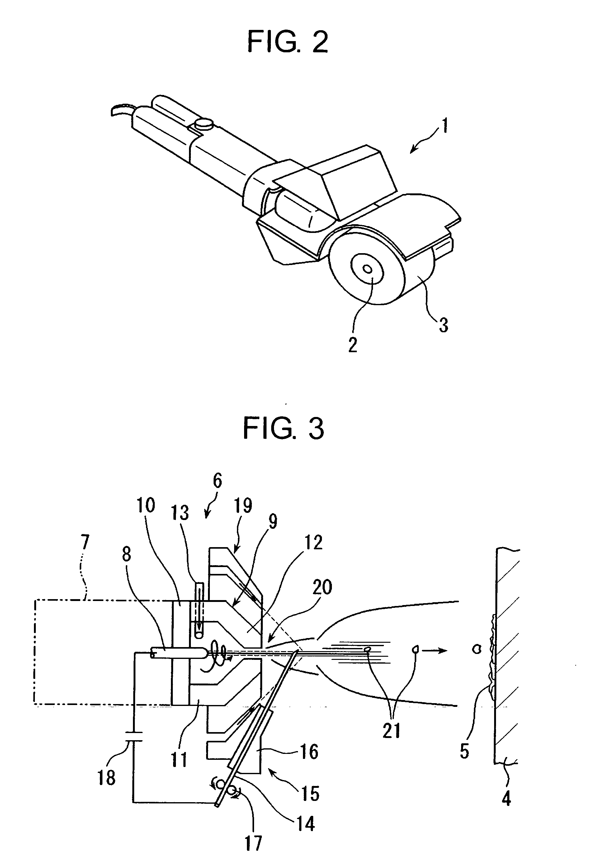
[0057]FIG. 2 is a perspective view of an exemplary grinding tool used in this example.

[0058] The grinding tool 1 is an electric grinding tool called as a grinding roller type sander. In the grinding tool 1, sandpaper 3 is attached to a roller 2. A surface of a damaged portion of steel is ground by rotation of the roller 2. Abrasive grains of silicon carbide, alumina, or the like having grain size number of #20 to #40 (average grain size: 1000 to 425 μm) are firmly fixed on the sandpaper 3 with resin binder. When the steel surface...


PUM

PropertyMeasurementUnit
Areaaaaaaaaaaa
Surface roughnessaaaaaaaaaa
Adhesion strengthaaaaaaaaaa

Abstract

In the application of plasma spraying to a metal body, it is intended to attain reduction of spraying cost and improvement of working efficiency in roughening operation while maintaining anticorrosive effects. An adhesion strength of spray coating comparable to that obtained in the conventional combination of blast treatment and gas flame spraying can be realized even if roughening is conducted with the use of simple tools by performing in advance such a roughening treatment that the average roughness (Ra) of surface of thermal spray subject falls within the range of 2 to 10 μm with the use of a grinding tool and thereafter carrying out thermal spraying under such conditions that the average area of each of molten particles when molten particles of a thermal spray material have stuck to the surface of thermal spray subject falls within the range of 10000 to 100000 μm2. In the roughening by means of grinding tools, large-scale apparatus is not needed as different from the blast treatment, and portable small tools can be used in overhead location work at field repair. The scattering of powder resulting from grinding is slight so that the danger of environmental pollution is low.

Description

TECHNICAL FIELD [0001] The present invention relates to a method of thermal spraying for forming a metal spray coating for corrosion prevention on a surface of a metal body. More particularly, the present invention relates to a method of thermal spraying suitable for field repair of a steel structure. BACKGROUND ART [0002] Conventionally, a coating is generally used for preventing corrosion in steel structures such as a steel tower, a bridge, an elevated structure, and a tank. The coating has problems that a coating cost is expensive, a useful life is limited, and a repair cost is also expensive because regular recoating is required. Thus, as a measure to prevent corrosion that can replace the coating, a construction method is proposed in which a spray coating is formed on a steel surface. For example, Patent Reference 1 describes an anticorrosive structure for a steel structure in which thermal spraying is performed for a portion of the steel structure that is placed in a bad envir...

Claims


Application Information

Patent Timeline
IPC IPC(8): B05D1/08C23C4/00E01D1/00C23C4/02C23C4/08C23C4/12C23C4/18E01D19/08E01D22/00H05H1/26
CPCC23C4/02C23C4/18C23C4/12
Inventor IMAIZUMI, YUKIOKAMAKURA, HIROKISAKURADA, TOSHIOYAMADA, KENICHIISHIBASHI, KATSUHIKO
Owner KYUSHU ELECTRIC POWER CO INC
Learn More