

Organic electroluminescent element and photocatalyst containing coating solution for organic electroluminescent element
a technology of electroluminescent elements and coating solutions, which is applied in the direction of electrical equipment, natural mineral layered products, chemical instruments and processes, etc., can solve the problems of high cost, high yield and cost, and require an expensive vacuum device, so as to achieve high-precision activation of photocatalysts
- Summary
- Abstract
- Description
- Claims
- Application Information
AI Technical Summary
Benefits of technology
Problems solved by technology
Method used
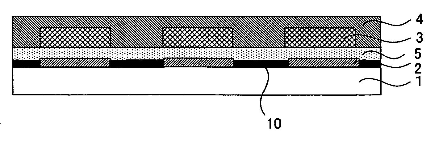
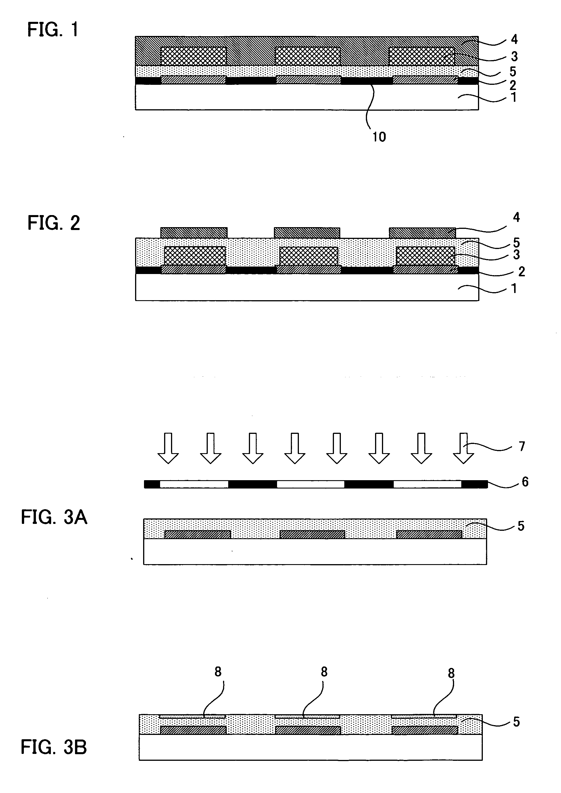
Image

Examples
example 1
(Cleaning of the Substrate with the First Electrode Layer Formed)
[0122] A substrate with a first electrode layer, having an ITO layer (first electrode layer) formed in a pattern on a 150 mm square glass substrate was washed by ultrasonic cleaning in a solvent containing an isopropyl alcohol and an acetone.
(Formation of the Photocatalyst Containing Layer)
[0123] Subsequently, by mixing and dispersing a photocatalyst containing solution (coating solution 1) having the following composition, and containing a photocatalyst and a liquid repellency providing agent, and a light emission characteristic material containing solution (coating solution 2) having the following composition, and containing a light emission characteristic material, a photocatalyst containing coating solution for an organic EL element (coating solution 3) was provided. The photocatalyst containing layer forming coating solution for an organic EL element was coated onto the above-mentioned substrate with a first ...
example 2
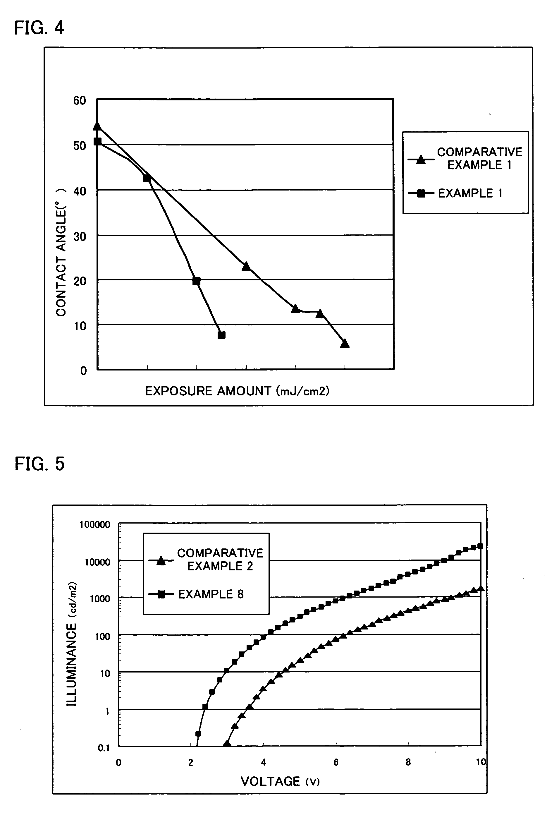
[0126] A photocatalyst containing layer was formed in the same manner as in the example 1 except that the silver acetate in the light emission characteristic material containing solution was changed to a camphorsulfonic acid, and energy irradiation was carried out using a high pressure mercury lamp (254, 365 nm) by a 70 mW / cm2 illuminance. The exposure amount necessary for having the contact angle of the photocatalyst containing layer with the distilled water to be 10° at the time is shown in the table 1 (the value in the case the exposure amount necessary for having the contact angle of the photocatalyst containing layer with the distilled water to be 10° in the above-mentioned comparative example 1 is provided as 1).
example 3
[0127] A photocatalyst containing layer was formed in the same manner as in the example 1 except that the silver acetate in the light emission characteristic material containing solution was changed to a silver acetyl acetonate complex, and energy irradiation was carried out using a high pressure mercury lamp (254, 365 nm) by a 70 mW / cm2 illuminance. The exposure amount necessary for having the contact angle of the photocatalyst containing layer with the distilled water to be 10° at the time is shown in the table 1 (the value in the case the exposure amount necessary for having the contact angle of the photocatalyst containing layer with the distilled water to be 10° in the above-mentioned comparative example 1 is provided as 1).
PUM
| Property | Measurement | Unit |
|---|---|---|
| Fraction | aaaaa | aaaaa |
| Percent by mass | aaaaa | aaaaa |
| Percent by mass | aaaaa | aaaaa |
Abstract
Description
Claims
Application Information