Design strategies for corrosion mitigation

a technology of membrane electrodes and corrosion mitigation, which is applied in the direction of cell components, sustainable manufacturing/processing, and final product manufacturing, etc., can solve the problems of affecting the function and/or affecting the efficiency of the fuel cell, and consuming precious metals

Inactive Publication Date: 2007-03-15
GM GLOBAL TECH OPERATIONS LLC
View PDF28 Cites 6 Cited by
  • Summary
  • Abstract
  • Description
  • Claims
  • Application Information

AI Technical Summary

Benefits of technology

[0015] In accordance with the general teachings of the present invention, new and improved membrane electrode assemblies for fuel cells, such as but not limited to PEM fuel cell systems, are provided.

Problems solved by technology

The catalytic particles are typically costly precious metal particles.
These membrane electrode assemblies are relatively expensive to manufacture and require certain conditions, including proper water management and humidification, and control of catalyst fouling constituents such as carbon monoxide (CO), for effective operation.
One problem that has been encountered concerns bipolar plate corrosion (particularly for metallic bipolar plates) involving the MEA or in proximity to the MEA, which could potentially impair the function and / or efficiency of the fuel cell.
Most MEA designs, however, incorporate a subgasket in the above described boundary region that differentiates the area of the MEA involved in electrochemical processes from that area which does not take part in useful electrochemical processes.
Normally this will result in formation of water, as well as a minute amount of hydrogen peroxide.
On the other hand, in areas of the bipolar plate where stagnant flow regions exist (e.g., manufacturing-related indentations (referred to as “dimples”) without active flow, regions along the MEA perimeter where there are no more flow-field channels, and / or any region of the active area of a bipolar plate that does not permit continuous flow of reactive gases during fuel cell operation) the concentration of both H2O2 and HF can increase substantially, thus forming a severe corrosive environment for metallic bipolar plates, for many of the typically applied coatings (e.g., metal oxides, metal nitrides, and / or the like), and for bipolar plate seal materials.

Method used


Image

  • Design strategies for corrosion mitigation
  • Design strategies for corrosion mitigation
  • Design strategies for corrosion mitigation

Examples


Embodiment Construction

[0032] The following description of the preferred is merely exemplary in nature and is in no way intended to limit the invention, its application, or uses.

[0033] In accordance with the general teachings of the present invention, systems and methods are provided to eliminate or at least reduce the incidence and / or degree of bipolar plate corrosion, especially of those bipolar plates comprised of stainless steel, as well as the elimination or reduction of surface coating degradation (e.g., metal oxides and / or organic coatings (e.g., silicon oxide and / or the like).

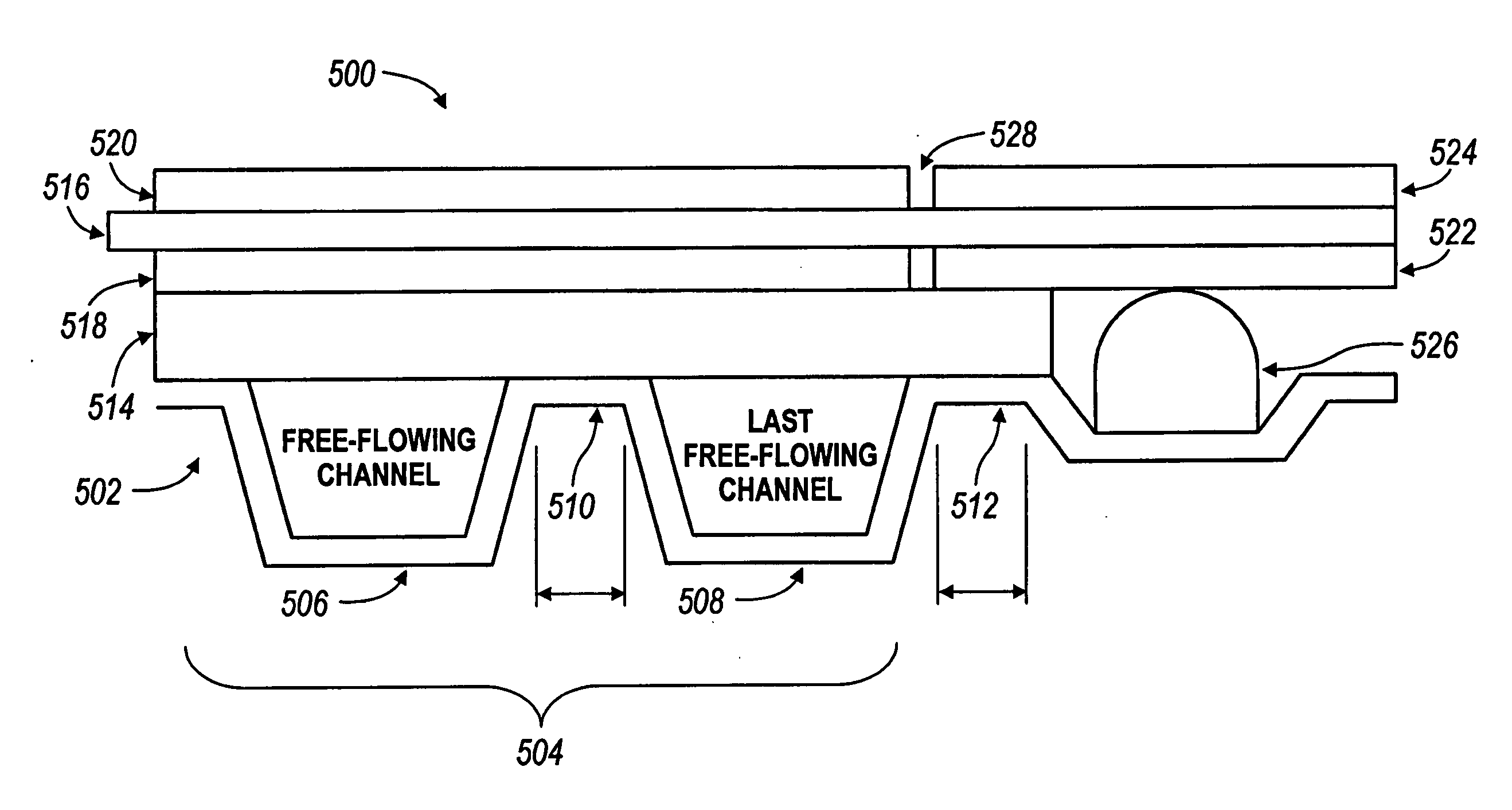
[0034] By way of a non-limiting example, all areas of the active area of the MEA (i.e., areas which contain proton-conducting membrane, Pt / C catalyst, other fuel cell electrocatalysts known in the art (e.g., Pt alloys / C), and MPL) should have adjacent flow-field channels on both the anode and the cathode side which have actively driven reactant flow, i.e., there must be no stagnant regions like dimples (created by some bipo...


PUM

PropertyMeasurementUnit
RHaaaaaaaaaa
electrode potentialsaaaaaaaaaa
conductiveaaaaaaaaaa

Abstract

Fuel cells are provided that are at least partially resistant to corrosion, including the use of components that are comprised of materials that are at least partially resistant to corrosion. The fuel cells include subgasket materials and designs, involving geometric arrangements of the subgasket that reduce oxygen permeation from, the cathode to the anode side of the membranes and/or hydrogen permeation from the anode to the cathode side of the membranes. In addition to using protonically non-conductive subgasket materials with lower oxygen and/or hydrogen permeabilities, versus ionomeric subgaskets which are protonically conducting and have high O2 permeation rates, the elimination of the microporous layer (e.g., coated onto the diffusion medium) directly beneath the permeable subgasket materials will also reduce production of corrosive species. The elimination of direct contact between the bipolar plate material surface and PFSA ionomer membrane material also prevents corrosion to the metal bipolar plates.

Description

BACKGROUND OF THE INVENTION [0001] 1. Field of the Invention [0002] The present invention relates generally to fuel cell systems, and more particularly to new and improved membrane electrode assemblies of fuel cell systems. [0003] 2. Discussion of the Related Art [0004] Fuel cells have been used as a power source in many applications. For example, fuel cells have been proposed for use in electrical vehicular power plants to replace internal combustion engines. In PEM-type fuel cells, hydrogen is supplied to the anode of the fuel cell and oxygen is supplied as the oxidant to the cathode. PEM fuel cells include a membrane electrode assembly (MEA) comprising a thin, proton transmissive, non-electrically conductive solid polymer electrolyte membrane having the anode catalyst on one of its faces and the cathode catalyst on the opposite face. The MEA is sandwiched between a pair of electrically conductive elements, sometimes referred to as the gas diffusion media components, that: (1) ser...

Claims


Application Information

Patent Timeline
Patent Type & Authority Applications(United States)
IPC IPC(8): H01M2/08H01M4/94H01M8/02
CPCH01M8/021H01M8/0245H01M8/0258Y02E60/521H01M8/04089H01M8/1023H01M8/1039H01M8/0284Y02P70/50Y02E60/50H01M8/0271
Inventor BUDINSKI, MICHAEL K.BRADY, BRIAN K.GASTEIGER, HUBERT A.NEWMAN, KEITH E.
Owner GM GLOBAL TECH OPERATIONS LLC
Why Eureka
Try Eureka