
Cellomics system

Inactive Publication Date: 2007-03-15
ON CHIP CELLOMICS CONSORTIUM
View PDF2 Cites 86 Cited by
  • Summary
  • Abstract
  • Description
  • Claims
  • Application Information

AI Technical Summary

Benefits of technology

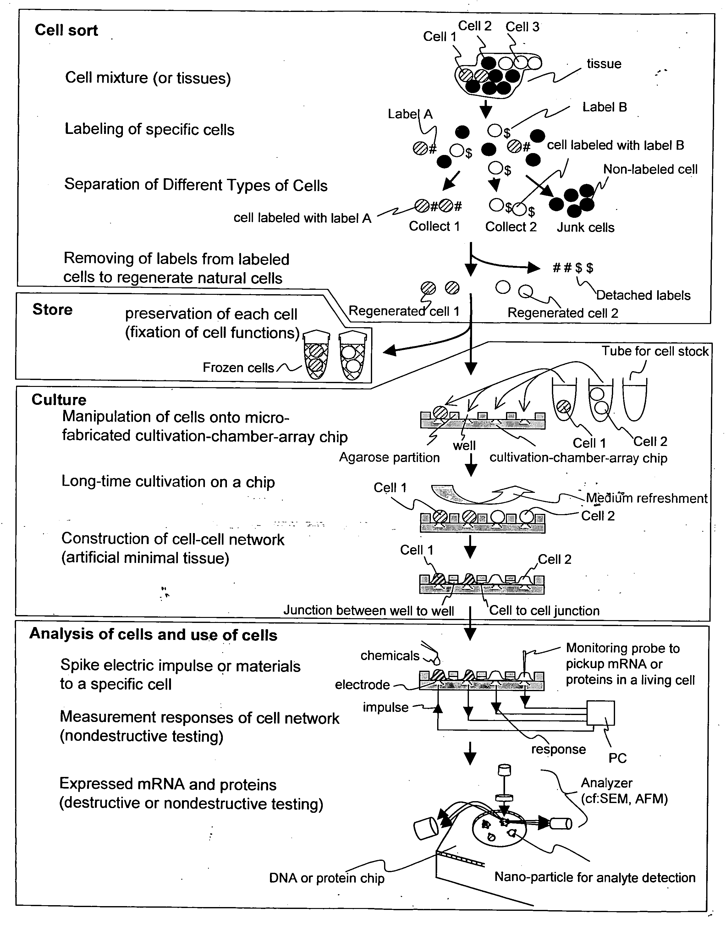
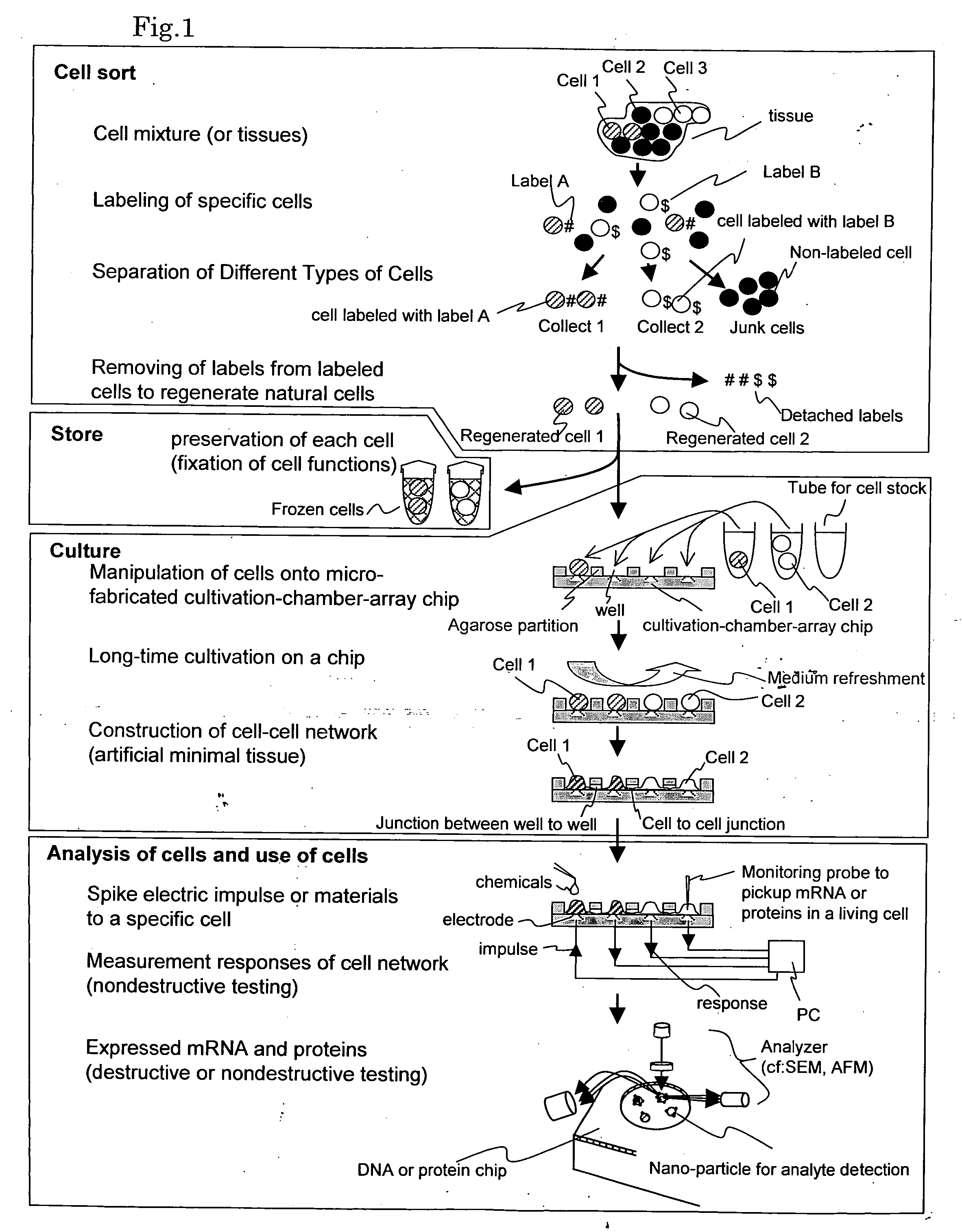
[0020] 4) A method of and apparatus for culturing each separated cell discretely for a long time: This technique is required to allow for not only a long time incubation of a single cell but also constitutive construction of and measurement for a cell network at a “single cell level” on a microchip.
[0024] An object of the present invention is to develop the researches on a cell assembly or a cell network constitutively constructed in the past into a pharmaceutical and medical screening system. The present system has the potentials of not only realization of a novel measurement technique at a cell level based on new understandings and recognition of the importance of “patterns” in a “cell network” not available so far, but also provision of new understandings concerning a life system based on the findings described above. In addition, if the cellomics system enabling measurement of a cell network base in place of animal experiments is successfully industrialized, high speed and low cost measurement using only a small number of samples will be possible not only in the fundamental researches but also in the field of screening technique for medical examination and food sanitary inspection, which would make great contributions to our health control.

Problems solved by technology

The main reason for this is that the relation between the sensitivity and reproducibility has not sufficiently be clarified in the researches using DNA micro-arrays.
If the sensitivity is just insufficient, it is simply required to further amplify the mRNAs in the form of cRNAs or cDNAs, but in the quantitative analysis, sometimes amplifying operations cause errors.
Even if it is tried to analyze gene expression (including protein translation) in discrete cells in the tissue, it is impossible to obtain a sufficient quantity of amplification products from a discrete cell with the conventional amplifying operation using, for instance, a DNA micro-array, and even when amplification is forcefully performed to a level allowing for analysis with a DNA micro-array, it is impossible to obtain data reflecting the actual abundance ratio of mRNAs.
However, it has been impossible to overcome the differences between humans and other animals, now the tendency for abolishing the animal experiments has been becoming stronger.

Method used


Image

  • Cellomics system
  • Cellomics system
  • Cellomics system

Examples


example)

(Example)

[0285] An example is described hereinafter with identification element made up of RNA aptamer as a labeling substance to label cell surface antigen CD4 and β-phycoerythrin as a marker substance in isolating and collecting cells bonded with the RNA aptamer. That is, cells presenting the cell surface antigen CD4 is specifically labeled with the β-phycoerythrin-modified RNA aptamer as described hereinabove, and then a cell isolation chip, which is a cell sorter formed on a plastic chip substrate as disclosed in Japan Patent Application 2004-379327.

[0286]FIG. 17 is a view showing a process flow of specifically labeling a cell presenting the cell surface antigen CD4 with the β-phycobiliprotein-modified RNA aptamer and thereafter isolating the cell with a cell sorter. The top-most part of FIG. 17 shows a sample 10 with two kinds of cells 3 and 4 in a mixed manner. The cells 3 present a cell surface antigen CD4 indicated by a triangular marked out in black with a reference numera...

example 6

(Example 6)

[0350] In the examples as described above, a pipet is described in each case as it has one function, while in Example 6, an example of a pipet having two functions is described.

[0351]FIG. 27(a) is a view showing a tip of a pipet 81 having two flow paths separated by a partition plate 82, and FIG. 27(b) is a view showing configuration in which a pipet 89 is provided inside a pipet 87 to form two flow paths.

[0352] In the configuration shown in FIG. 27 (a), by making a first flow path 83 sufficiently larger than a second flow path 84, and by designing a structure in which cell suspension can be supplied from the first flow path 83 and dilution can be supplied from the second flow path 84, the pipet 11 and the pipet 20 described in Example 2 can be integrated. It is needless to say that controls of the respective flow paths are carried out with respective independent syringe pumps.

[0353] In the configuration shown in FIG. 27(b), the inner pipet 89 has an inner diameter of ...

example 5

(Example 5)

[0839] In order to make the twenty-first embodiment of the present invention more effective, it is preferable to eliminate a charge of probe itself and introduce a large amount of minus charge to the free terminal of the probe. For instance, PNA (Peptide Nucleic Acid) in which a phosphodiester bond of synthetic oligonucleotide is changed to a peptide bond, or CAS (Cysteine Antisense Compound) which includes S-carboxydimethyl-L-cysteine as a base frame may be used as a non-charged probe.

[0840] Since main chains of the polymer PNA and CAS have no charge, an electrostatic repelling force does not work with the target polynucleotide. As they have amino group and carboxyl group on the terminals thereof respectively, when an amino group is used at the fixed terminal, the fee terminal is naturally changed to a negatively charged carboxyl group. Further it is possible to make the probe act quickly in response to the electrode on the surface of the substrate by introducing a larg...


PUM


Abstract

In labeling a cell, and separating and collecting the cell according to a degree of the labeling using a cell separator, effects on the cell is minimized and the use of the collected cell is facilitated, thereby, when labeling a cell, the cell is labeled in the state where interaction of each cell is retained. In the labeling, a specific labeling material present on a surface of a target cell is taken in the cell via a transporter, and the cell is dispersed one by one to separate the same with a cell separator. Immediately after the separation, the cell is put in a solution not containing the specific labeling substance to remove the specific labeling substance taken in the cell. This series of steps is continuously conducted with a cell separation chip.

Description

FIELD OF THE INVENTION [0001] The present invention relates to promotion of researches in the field of cellomics for comprehensively understanding vital functions as those of a cell assembly, and more particularly to measurement of expression of genes in discrete cells in the state where functions of each cell structure are preserved, namely in the state where interactions between cells are preserved. BACKGROUND OF THE INVENTION [0002] With the active researches in the fields of genomics or proteomics from the last decade of 20th century up to this day, data has been accumulated concerning types and quantities of genes in various cell groups each regarded as an assembly of cells. Especially, accumulation of data concerning precise comparisons among genome sequences different from species to species, or frequencies of expression of various genes in organs and tissues in one species has reached a level allowing sketchy descriptions of the life process. In the future, various active re...

Claims


Application Information

Patent Timeline
IPC IPC(8): G01N33/53
CPCG01N33/5061G01N33/566A01N1/0284B01L7/50
Inventor OKANO, KAZUNORIYASUDA, KENJI
Owner ON CHIP CELLOMICS CONSORTIUM
Learn More