

Ultrasonic knife
- Summary
- Abstract
- Description
- Claims
- Application Information
AI Technical Summary
Benefits of technology
Problems solved by technology
Method used
Image

Examples
embodiment 46
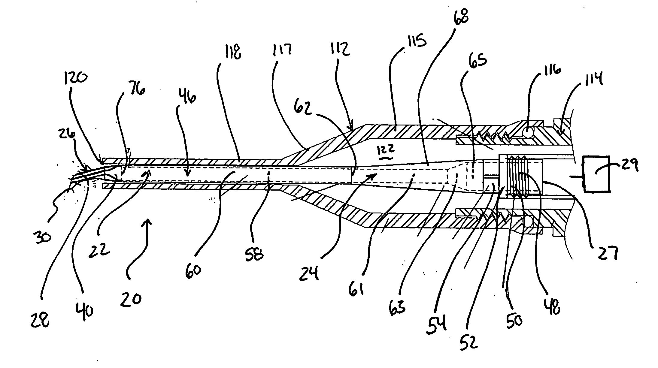
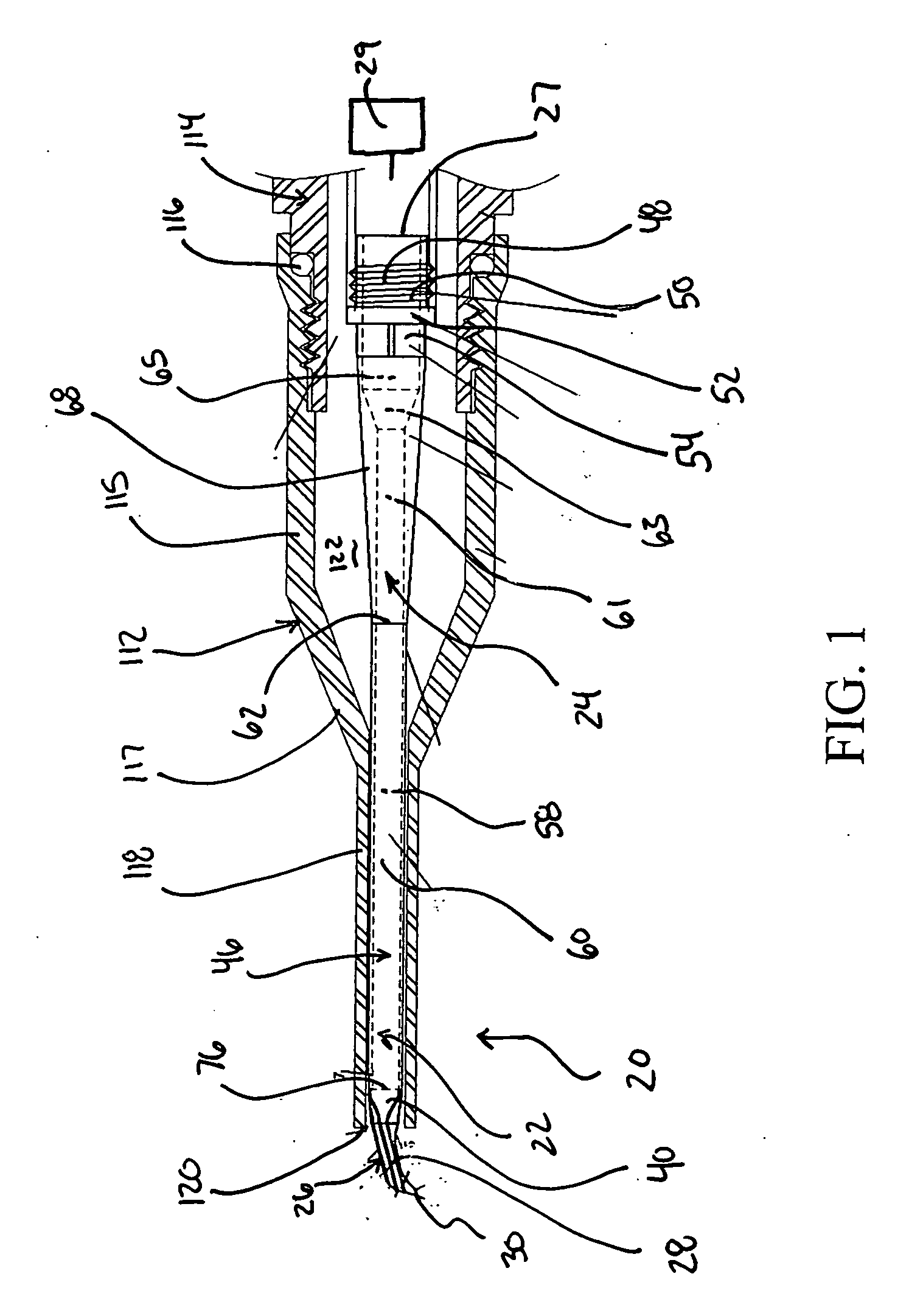
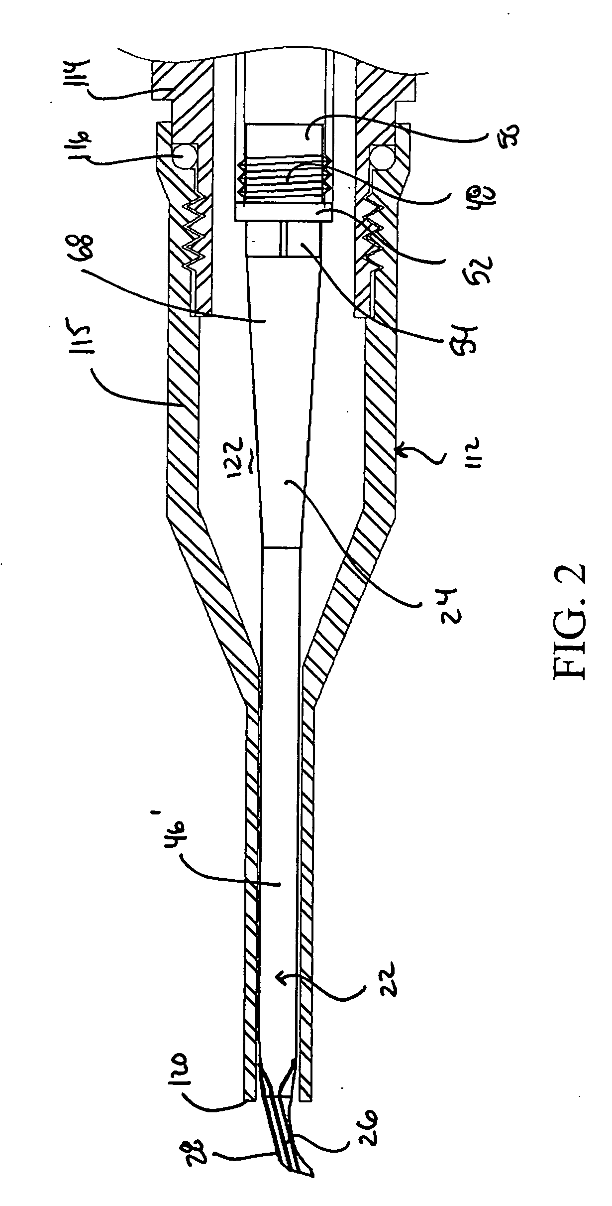
[0074] In a preferred embodiment, energy transmission section 24 includes shaft 46 (FIG. 1 featuring a hollow or internalized aspirating passageway embodiment, and FIG. 2 featuring a solid shaft or non-aspirating embodiment 46′) as well as connector 48 (or means for attachment) to a movement generator (schematically shown at 29 which is preferably in the form of an ultrasonic vibrating device such as one utilizing a piezoelectric transducer, although alternate movement generating devices are also featured under the present invention including, for example, alone or in conjunction with one or the other, fluid, acoustic, motor (e.g., offset cam), reciprocating piston or other movement generating means.
[0075] In a preferred embodiment shaft 46 includes a cylindrical shaft segment 60 that is preferably approximately 14 mm in length and 1 mm in diameter, although a variety of alternate cross-sectioned shaped, preferably straight shaft segments and lengths are featured under the subject m...
second embodiment
[0098] With reference to FIGS. 12, 15 and 19 there is described cutting device 722 under this second embodiment set which is well suited for cutting in quick and efficient fashion through softer cataracts (e.g., non-black and non-brunescent cataracts).
[0099] As seen from FIG. 15, for example, cutting device 722 features a tip 724 with modified blade 726 extending off of a transition section 40 similar to that described above for the FIG. 1 embodiment. The height H2 (FIG. 19) of blade 726 is preferably the same as H1 (FIG. 8A) with a range of 0.7 to 2.0 mm being well suited for the preferred usages of the present invention. With reference to FIGS. 15 and 19 there can be seen forward, flat edge 732 having an upper end point 728 and a lower (material contact) point 730. The opposite walls 733 and 734 of blade 724 preferably converge from thicker upper edge 736 to lower edge 738 in similar fashion of the convergence discussion above (both vertically and axially), but with a preferred up...
PUM
 Abstract
Description
Claims
Application Information