Variable optical attenuator

Active Publication Date: 2005-09-20
ASIA PACIFIC MICROSYST
View PDF12 Cites 15 Cited by
  • Summary
  • Abstract
  • Description
  • Claims
  • Application Information

AI Technical Summary

Benefits of technology

[0014]In accordance with one aspect of the present invention, the flexure spring holding said tilted mirror at one side, and the spring located between said tilted mirror and said actuator can be made of versatile materials, including silicon, ceramics, glass, metals, polymers, elastic mate

Problems solved by technology

However, they can not be minimized to meet the needs of high channel-count integration due to the bulky size of the stepping motor or the electromagnetic coil.
Essentially, the major drawbacks are their bulky size, long response time, difficulty of system integration and high cost.
The waveguide and LC VOAs, while being suitable for high channel-count integration, are lack of consistent and stable attenuation expressed in the form of high insertion loss (IL), high Polarization Dependent Loss (PDL), high Polarization Mode Dispersion (PMD) and sensitivity to ambient temperature.
However, the associated IL and back-reflection loss (BR loss) of MEMS VOAs can not be easily perfected due to the existing interfaces among different optical elements according to its nature of free space optical operation scheme.
The requirement of precise

Method used


Image

  • Variable optical attenuator
  • Variable optical attenuator
  • Variable optical attenuator

Examples


Example

The First Embodiment

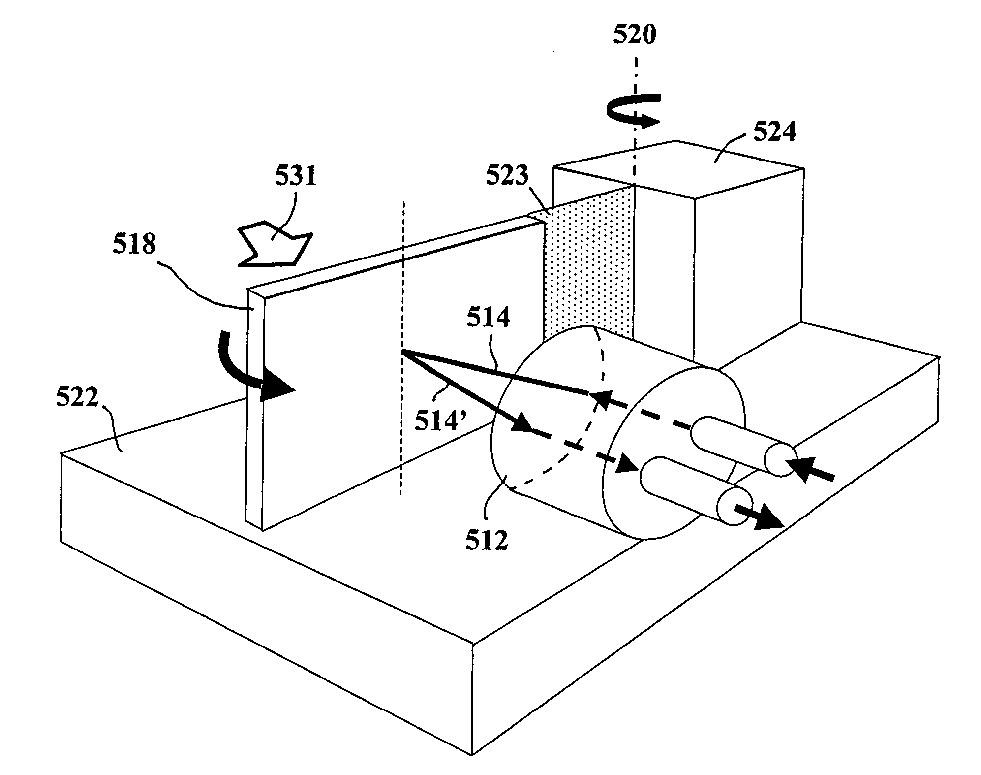
[0042]FIGS. 5A, 5B, 5C and 5D show the MEMS VOA device in accordance with the present invention. The MEMS VOA device 510 is made by using micromachining technology. The MEMS VOA device 510 comprises a tilted mirror 518 which is suspended and supported via flexure spring 523 by a post (or a pivot) 524 onto a substrate 522, and input and output optics and fibers 512, 513, 513′ arranged on top of a substrate 522. Once the actuator 530 is under an electrical load, this tilted mirror 518 will have in-plane rotational movement and in-plane displacement with respect to the pivot or upright axis 520, because a driving force 531 is generated by the actuator 530 and applied to the tilted mirror 518 on a contacting point 533 through flexure spring 532. In the other words, the tilted mirror 518 in present invention exhibits movement comprising planar rotational mirror deflection (denoted as ø541 in FIG. 5D) and planar parallel shifted mirror displacement (denoted as t545 in ...

Example

The Second Embodiment

[0046]FIGS. 6A and 6B show the device optical light path configuration for said MEMS VOA device 510 under normally close operation, or dark type VOA device configuration. In this case, original mirror position shown as the tilted mirror 618 is away from an optimal position of tilted mirror 618′, where device achieve minimum coupling loss at this position, or no attenuation. The reflected light beam 614′a from the b point to the d point is away from the optimal reflected light beam 614′c from the b′ point to the c point. The corresponding attenuation value of MEMS VOA device 510 in FIG. 6A is set to be fully attenuation, i.e., no light transmitted. When the actuator 630 drives the tilted mirror 618 with a force 631 to move to an optimal position of tilted mirror 618′, the incident light beam 614 transmits toward the tilted mirror 618′ at the point b′ and is reflected toward the point c, the corresponding reflected light beam path is 614′c which means the best cou...

Example

The Third Embodiment

[0047]In the present invention, the actuator 530 or 630 drives the tilted mirror to move with a force load 531 or 631 at the contacting point 533 or 633 through a spring 532 or 632, as shown in FIGS. 5 and 6. The spring 532 or 632 is designed to be effectively transfer force or displacement generated from actuator 530 or 630 to tilted mirror 518 or 618, and is designed to be a structure including a portion of flexure part that is capable of absorbing the environment mechanical shock or vibration without disturbing the actuation operation along the direction of force 531 or 631 when said MEMS VOA device 510 under operation. For example, the flexure part of said spring 532 or 632 could be a meander-shaped high-aspect-ratio single crystal silicon spring which is able to properly make mirror movement comprising the parallel mirror shifted displacement and rotational mirror deflection, and can reduce the influence of mechanical shock or vibration with respect to direc...


PUM


Abstract

A variable optical attenuator for providing a new light attenuation mechanism based on using at least one of tilted mirrors to change and control the beam direction of reflected light beam toward output optical port in a two dimensional light path configuration is demonstrated to achieve the light attenuation in terms of changing and controlling the coupling loss among input optical port, reflective tilted mirrors, and output optical port. The tilted mirror is supported and connected by a suspended flexure spring at one side. This suspended spring is connected with tilted mirror at one side and is anchored on a substrate at the other side via a post (or a pivot). When the tilted mirror is driven by an actuator to generate movement including rotational mirror deflection and parallel mirror shifted displacement, the reflected light beam path is changed according to the particular mirror positions. The attenuation value is modified and controlled by the coupled light of reflected light beam to output port. The structure and materials of variable optical attenuator is designed and chose to be robust to environment mechanical and thermal noise.

Description

BACKGROUND OF THE INVENTION[0001]1. Field of the Invention[0002]The present invention relates to the fiber optical components used in telecommunications. More particularity, the present invention discloses a variable optical attenuator (VOA) which is able to control the amount of light power propagating in optical networks.[0003]2. Description of the Prior Art[0004]The industry of fiber optical communications has already proven to be indispensable for the achievement of low noise, long distance telecommunication with a heretofore-unrealizable high bandwidth. Within an optical communication network a Variable Optical Attenuator (VOA) is an important basic component with the function of controlling the propagated level of light power, such as a single-channel VOA or a VOA array.[0005]Currently, there are four kinds of commercially available VOA devices in the market, they are opto-mechanical VOA devices using stepping motor or magneto-optical crystal, and VOA devices based on waveguid...

Claims


Application Information

Patent Timeline
IPC IPC(8): G02B6/00G02B6/35G02B6/26H02N2/02H02N2/04
CPCG02B6/266G02B6/3512G02B6/3566G02B6/3584G02B6/3594
Inventor CHEN, CHIHCHUNGLEE, CHENGKUO
Owner ASIA PACIFIC MICROSYST
Why Eureka
Try Eureka