Smokeless cooker

Inactive Publication Date: 2007-03-22
SHINPO IND
View PDF5 Cites 13 Cited by
  • Summary
  • Abstract
  • Description
  • Claims
  • Application Information

AI Technical Summary

Benefits of technology

[0009] The invention is embodied in a smokeless cooker that can, when discharging exhaust gas generated from the cooker outdoors or indoors, almost completely remove oily smoke and odor from the exhaust gas.

Problems solved by technology

However, since such maintenance requires a considerable expense, owners and operators of barbecue restaurants sometimes neglect to perform such maintenance services in a timely manner.
When such maintenance is neglected, however, a large amount of fat, oil, or the like may accumulate inside the duct and on the filters.
A duct fire may happen when fire comes in contact with the accumulated fat and oil, which can catch fire inside the duct.
In the conventional non-duct type cooker, however, since the exhaust gas is not satisfactorily cleaned inside the cooker body, it is difficult to completely remove the oily smoke and odor from the exhaust gas generated from the cooker.
Although the exhaust gas has been cleaned, it may still be somewhat hot since it has come from the roasting surface of the cooking section.
When the cooker is used in a restaurant, a party hall, or the like, guest seats must therefore be disposed away from the discharge louver, and the possible layout of the guest seats is thereby restricted.

Method used


Image

  • Smokeless cooker
  • Smokeless cooker
  • Smokeless cooker

Examples


second embodiment

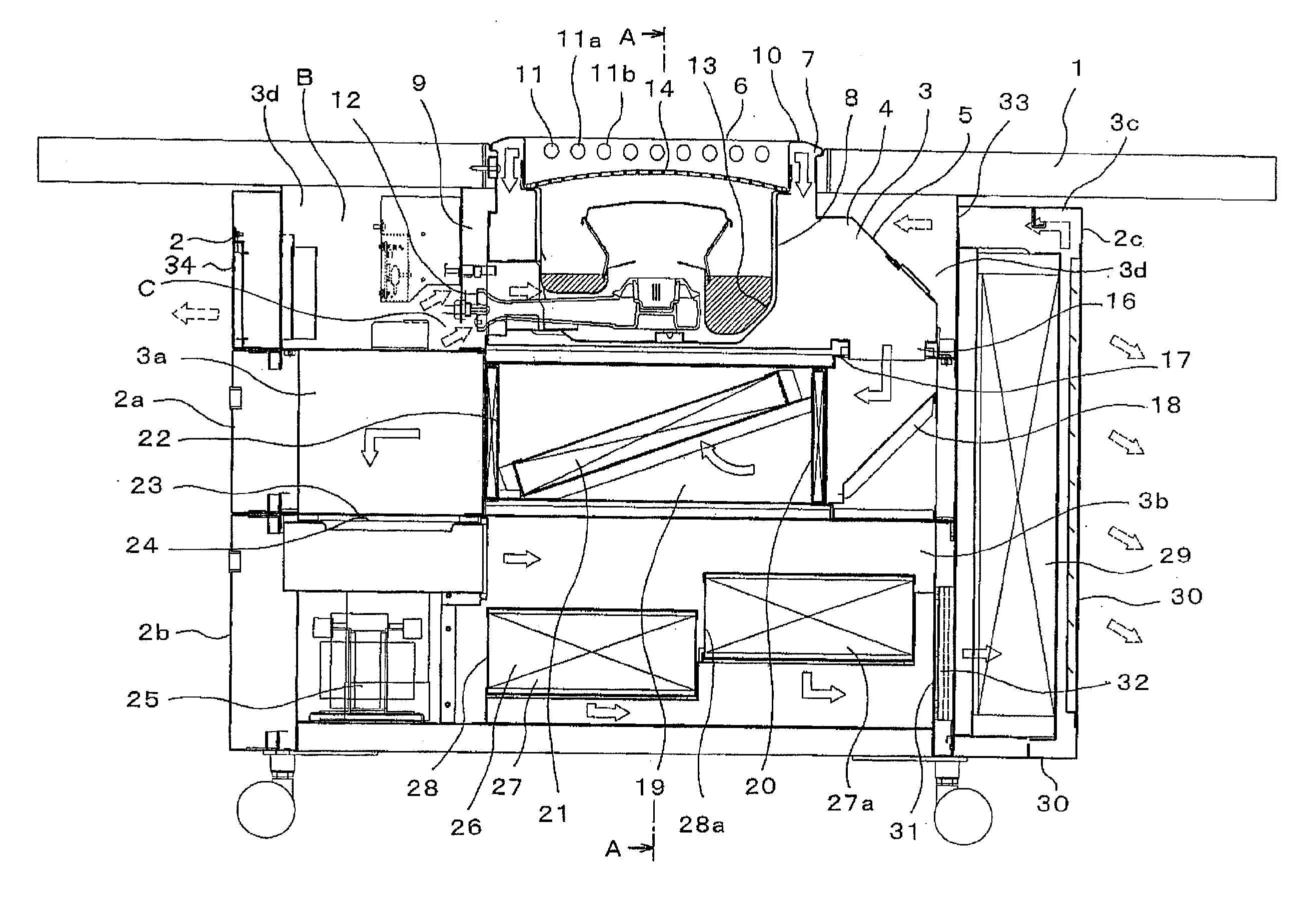
[0068] In the cooker in accordance with this second embodiment, the air supplied for combustion is preferably approximately 50% of total amount of the exhaust gas. Note that the amount of the exhaust gas supplied into the upper box 2 with respect to the total exhaust gas can be controlled by adjusting the opening area of the exhaust opening 30 provided to the side box 2c.

[0069] Further note that, by sending a part of the cleaned exhaust gas into the upper box 2 as described above, the outer face of the outer box 5 disposed in the upper box 2 can be cooled, and thus the temperature of the side wall of the upper box 2 can be prevented from rising unduly.

[0070] To facilitate recycling of materials, each of the boxes 2, 2a, . . . , may be made of metal. The box body with an open front face and the cover attached to the outside of the box body may be made of a plastic. To facilitate recycling when disassembling the boxes, a plastic cover may be detachably attached to the box body.

[007...

embodiment 3

[0082] The separable smokeless cooker in accordance with the embodiment 3 is characterized in that the IH heater is employed as the heat source. The IH heater generates heat by induction heating of an iron plate. In a gas heater or the like, radiant heat and heat convection utilizing far infrared radiation are used. An IH heater uses a heat input amount and a heating temperature with respect to the cooked object that are low in comparison with gas heating or the like. It is thus known that roasting a meat using an IH heater generates less oil smoke in comparison with a gas flame. This is because no flame is present to burn meat juices generated from the heated meat.

[0083] In other words, the separable smokeless cooker in accordance with this embodiment can reduce the generation of oily smoke. The load on the filters and the active charcoal in the deodorizing unit are thereby reduced. Accordingly, the replacement cycle of the consumable parts can be extended, which yields a reduced o...


PUM

PropertyMeasurementUnit
Fractionaaaaaaaaaa
Ratioaaaaaaaaaa

Abstract

A smokeless cooker includes a table located indoors, with a cabinet, which may include a plurality of individual boxes stacked and assembled together, below the table. A gas-discharge flow path leads from the cabinet to the outdoors. The cabinet includes an inner box with an open upper portion in an upper opening section of an outer box. An installed cooking means is located inside the inner box. A suction flow path is formed outside the inner box, with a suction hole in the inner wall of the suction flow path above a heating surface of the installed cooking means. The gas-discharge flow path includes a fat / oil filtering section, an absorption deodorizing section, a HEPA filter and a fan. A duct leading to the outdoors is present at the downstream side of the HEPA filter.

Description

CROSS-REFERENCE TO RELATED APPLICATIONS [0001] This application is a continuation under 35 U.S.C. §120 of International Patent Application Serial Number PCT / JP2004 / 017067, filed Nov. 17, 2004, which claims priority based on Japanese Patent Application Serial Number 2003-388387, filed on Nov. 18, 2003.BACKGROUND OF THE INVENTION [0002] The invention relates generally to devices and apparatus for cooking foods. More particularly, the invention is embodied in a smokeless cooker that filters its exhaust gas through a HEPA filter. [0003] Conventionally, in order to discharge the exhaust gas generated from a cooker disposed in a barbecue restaurant or the like to the outside, the cooker is connected to a duct, with a deodorizing unit connected at the downstream side of the duct. In general, a centralized duct system has been employed that filters oily smoke and odor out of the exhaust gas generated from plural cookers and discharges the exhaust gas to the outside. [0004] Duct and deodoriz...

Claims


Application Information

Patent Timeline
IPC IPC(8): F24C15/20A47J36/38A47J37/06A47J37/07
CPCA47J36/38F24C15/2042A47J37/0781A47J37/0704A47J37/0754A47J37/0786B01D46/00
Inventor OTA, MASUO
Owner SHINPO IND
Why Eureka
Try Eureka