Passively Q-Switched Microlaser With Controllable Peak Power Density

a microlaser and peak power density technology, applied in laser details, laser optical devices, semiconductor lasers, etc., can solve the problems of low efficiency, low efficiency, and inability to disclose a means of change, and achieve the effect of varying the laser output characteristics in a simple and inexpensive way

Active Publication Date: 2007-03-22
LUMENTUM OPERATIONS LLC
View PDF10 Cites 30 Cited by
  • Summary
  • Abstract
  • Description
  • Claims
  • Application Information

AI Technical Summary

Benefits of technology

[0047] A simplified design is disclosed for varying the optical path lengths of the lasing (gain) and saturable absorber media within the cavity of a passively Q-switched microchip laser. By varying the optical path lengths by way of a transverse translation of the microchip, control of the output pulse energy, pulse duration, peak power and peak power density is enabled in a simple and inexpensive way.
[0048] The basic configuration according to this disclosure is a laser cavity comprising of a gain medium blo...

Problems solved by technology

However, they have intrinsic disadvantages compared to passively Q-switched lasers in terms of size, complexity, cost, ruggedness.
This patent does not disclose a means for changing the length of the gain media in the optical cavity and all figures in the patent show a cavity gain media of constant length.
However, in the disclosed invention the variation of the optical length of the cavity is very limited (less than one wavelength), which is not enough for yielding a broad range of control of the output performance.
The cavity is also misaligned, whereby losses are increased and performance reduced.
This mechanism adds complexity, and further increases the likelihood of misalignment when adjusting the output parameters.
Semiconductor saturable absorbers are disclosed by Tan (U.S. Pat. No. 6,842,466, Nanyang Technological University), which have a limited range of achievable performance.
As the disclosed laser is based on a coating with variable transmittance across the output aperture, the solution is difficult to implement in manufacturing, as coatings have to be applied individually to each laser chip.
The five disclosures described above concern non-monolithic laser cavities, which induce several important limitations: sensitivity of laser performance to misalignment and vibrations.
In particular, drift of performance with temperature or over time is very common in this geometry;...

Method used


Image

  • Passively Q-Switched Microlaser With Controllable Peak Power Density
  • Passively Q-Switched Microlaser With Controllable Peak Power Density
  • Passively Q-Switched Microlaser With Controllable Peak Power Density

Examples


Embodiment Construction

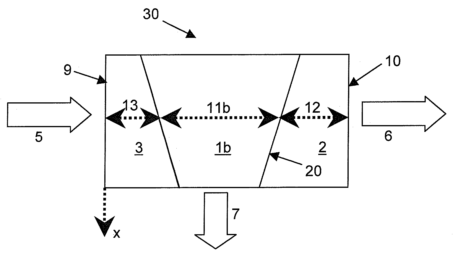
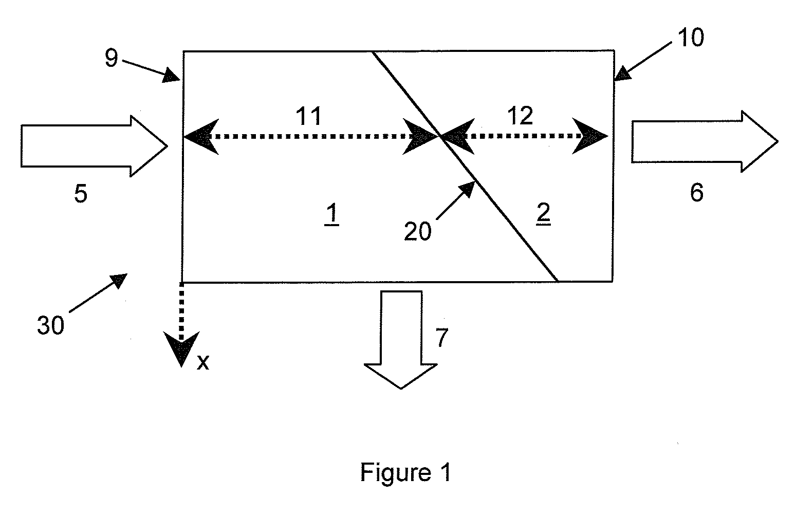
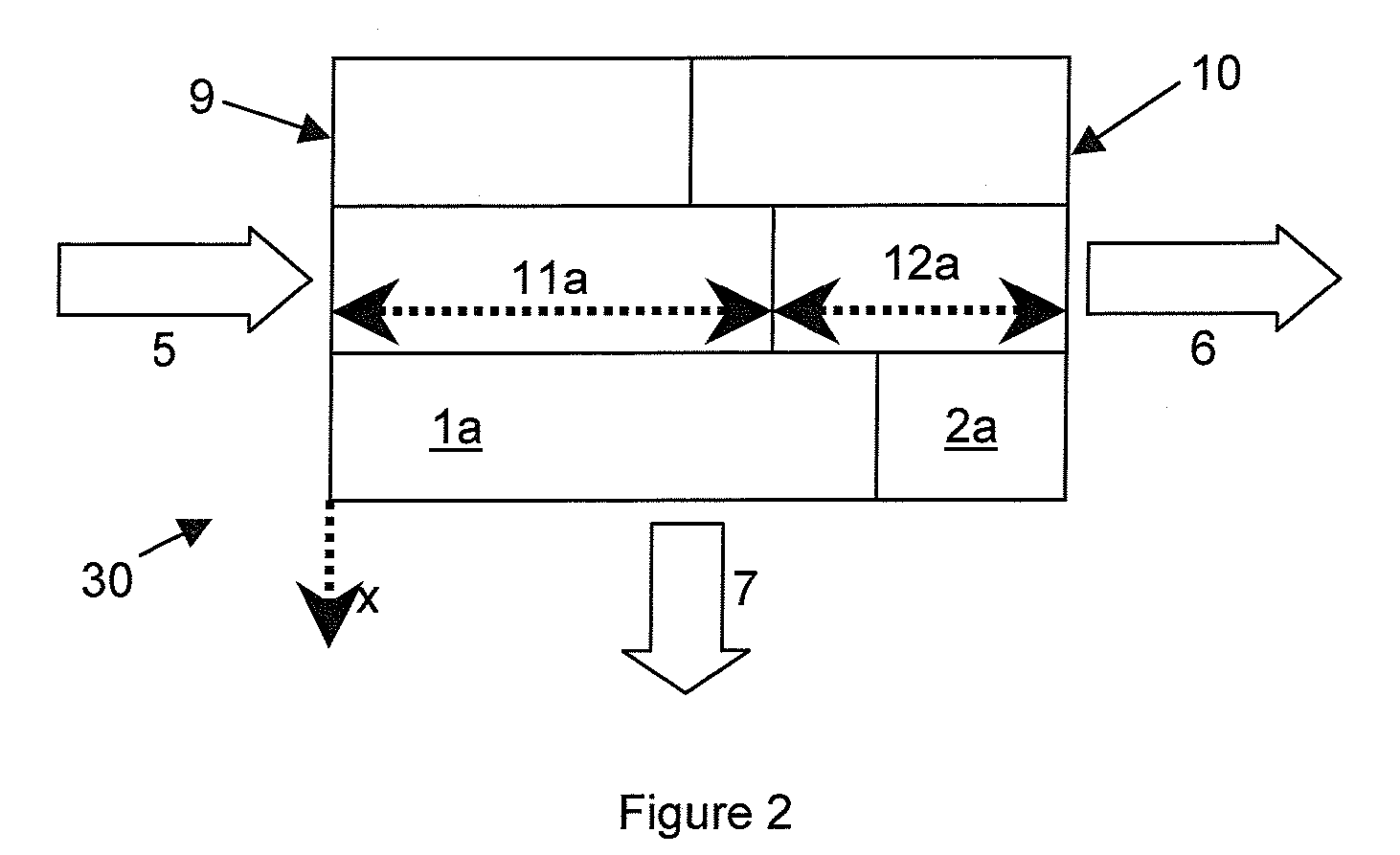
[0065] The present invention provides for an easy way to control the pulse energy, pulse duration or peak power density of passively Q-switched microlasers by designing the geometry of the laser cavity (e.g. wedged-shaped materials) so that the optical path in the active medium and / or the saturable absorber can be varied by simple displacement of the microlaser. Such structures can be produced using standard techniques: diffusion bonding (or optical contacting) of wedged plates, or liquid phase epitaxy of one material on a wedged substrate of the other material. In addition, combining such a microlaser with variable-focus optics allows the peak power density of the output laser beam to be controlled.

[0066] Such a laser system can be used for direct application, or seed a subsequent amplifier or harmonic generation stages.

[0067] A first exemplary embodiment is described in FIG. 1, in which a microchip 30 comprises a wedge-shaped gain medium 1, and a wedge-shaped saturable absorbe...


PUM


Abstract

Geometrical design of laser microchips is disclosed that allows variation of the optical path length in the different media by simple displacement of the microchip, the movement having a non-zero projection orthogonal to the pump beam. The concept can be implemented to vary optical loss in the lasing cavity, the absorbed pump power, or the optical length of the cavity. Passively Q-switched microchip laser output performance can thus be controlled by simple transverse displacement of the microchip relative to the pump beam. The above microlaser can be combined with voltage-controlled variable-focus output optics in order to control the peak power density of the laser pulses.

Description

CROSS REFERENCE TO RELATED APPLICATIONS [0001] This application claims priority of U.S. Provisional Patent Application No. 60 / 718,780 filed Sep. 20, 2005, entitled “A modular passively q-switched microlaser with controllable peak power density, coaxial package platform and assembly process” which is incorporated herein by reference for all purposes.FIELD OF THE INVENTION [0002] The present invention relates to pulsed microchip lasers, in particular those having tunable output performance based on variably filled cavity and variable-focus optics. BACKGROUND OF THE INVENTION [0003] Passively Q-switched microchip lasers have many advantages: they allow the realization of low-cost, compact and robust laser sources. Because of the short cavity length, they are capable of generating pulses with high peak power, which are particularly convenient for generation of harmonics (e.g. ultraviolet lasers). High peak power is of primary interest for many applications such as marking, excitation of...

Claims


Application Information

Patent Timeline
IPC IPC(8): H01S3/11
CPCH01S3/005H01S3/2375H01S3/0405H01S3/042H01S3/0602H01S3/0606H01S3/0612H01S3/0627H01S3/06754H01S3/094053H01S3/094076H01S3/09415H01S3/101H01S3/1022H01S3/1026H01S3/106H01S3/108H01S3/113H01S3/1611H01S3/1643H01S3/025
Inventor FEVE, JEAN-PHILIPPELANDRU, NICOLAS
Owner LUMENTUM OPERATIONS LLC
Why Eureka
Try Eureka