

Alkaline storage cell and hydrogen storage alloy for negative electrode or alkaline storage cell
- Summary
- Abstract
- Description
- Claims
- Application Information
AI Technical Summary
Benefits of technology
Problems solved by technology
Method used
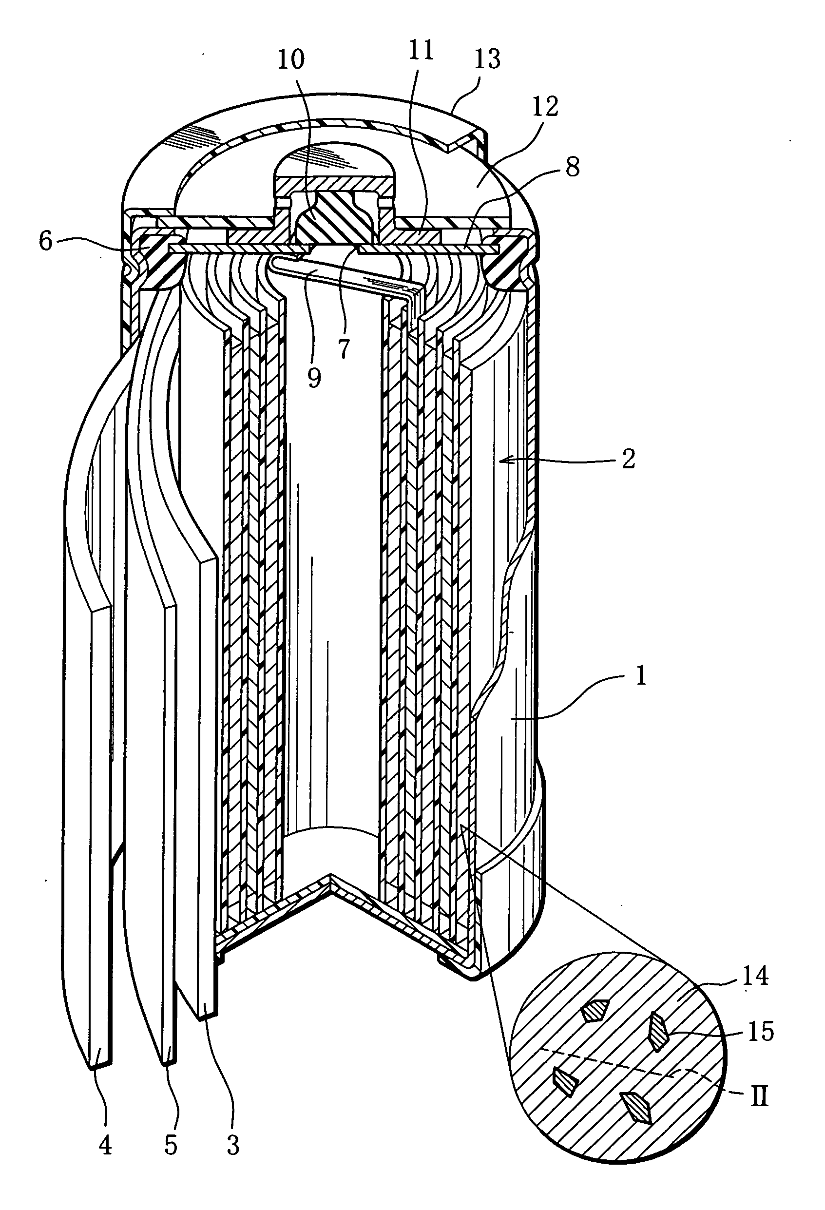
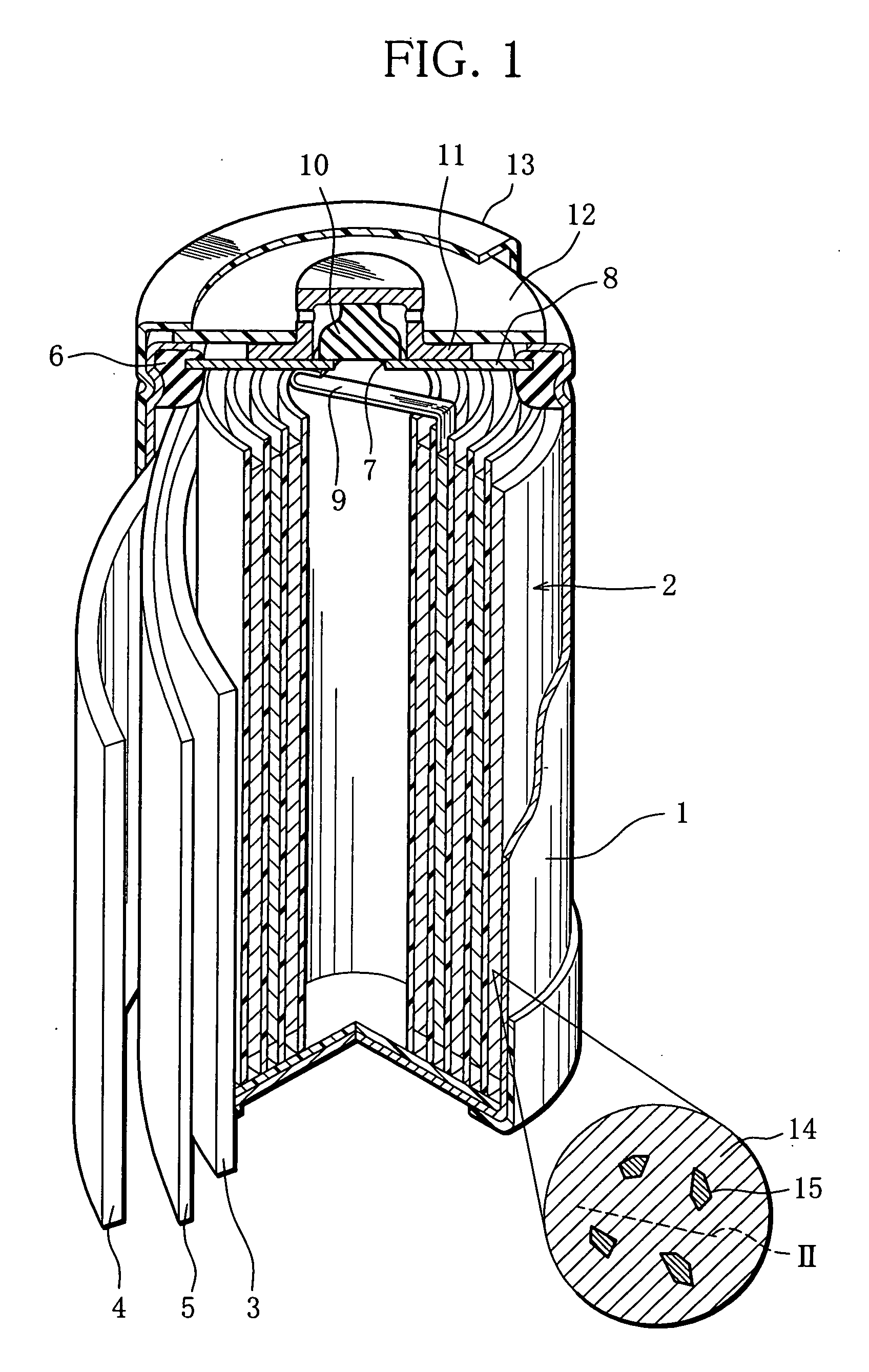
Image

Examples
example 1
1. Preparation of a Negative Electrode
[0067] Metal materials were measured out to produce the composition (La0.7Y0.3)0.89Mg0.11Ni2.95Mn0.15Al0.35 and mixed. The mixture was melted in a high-frequency melting furnace and formed into an ingot. The ingot was heated in an argon atmosphere of temperature 1000° C. for 10 hours to thereby change the crystal structure of the ingot to a superlattice structure such that AB5-type structure and AB2-type structure are merged. Then, the ingot was mechanically pulverized in an inert gas atmosphere and sieved to thereby obtain rare earth-Mg—Ni hydrogen storage alloy powder having the above composition. The average particle size corresponding to weight integral 50% of the rare earth-Mg—Ni hydrogen storage alloy powder obtained, measured using a laser diffraction-scattering particle-size distribution measurement device, was 50 μm.
[0068] To 100 mass-parts of the alloy powder obtained, 0.5 mass-parts of sodium polyacrylate, 0.12 mass-parts of carbox...
PUM
| Property | Measurement | Unit |
|---|---|---|
| Fraction | aaaaa | aaaaa |
| Fraction | aaaaa | aaaaa |
| Fraction | aaaaa | aaaaa |
Abstract
Description
Claims
Application Information