Aerodynamic air gun projectile

a gas-propelled and projectile technology, applied in the field of gas-propelled projectiles, can solve the problems of significant large losses, appreciable range loss, and inability to accelerate the compression work represented by the column of highly compressed air in the bore, so as to reduce the turbulent airflow, enhance the laminar flow, and reduce the overall drag

Inactive Publication Date: 2007-04-05
PONTIERI JAMES M
View PDF40 Cites 31 Cited by
  • Summary
  • Abstract
  • Description
  • Claims
  • Application Information

AI Technical Summary

Benefits of technology

[0031] According to another aspect of the invention, the vanes can also extend axially along at least a portion of the outer surface of the skirt portion of the projectile adjacent its waist. This arrangement is believed to reduce turbulent airflow adjacent the waist of the skirt portion, and thereby enhance laminar flow, reducing overall drag and increasin

Problems solved by technology

The energy stored in the spring is largely converted to work of compression performed as a nearly adiabatic process compressing the air ahead of the piston, but significantly large losses arise in the process of transferring kinetic energy of motion to the projectile from the compressed fluid.
Consequently, the friction of the work of compression represented by the column of highly compressed air in the bore is not available for further acceleration of the projectile as a secondary piston.
In general, the best prior art pellets have a skirt margin which is relatively stiff and unyielding, so that insertion into the breech end of the barrel, even when the breech is tapered, requires firm pressure by the user's thumb to perform the initial swaging operation.
The release of the projectile from the skirt portion while within the barrel will result in appreciable loss of range due to premature blow-by of the compressed air around the projectile, which has a substantially smaller diameter than the internal diameter of the gun barrel.
Additionally, the loss of contact of the pellet with rifling within the bore will adversely affect both range and accuracy, as will the round shape of the pellet.
The multi-part structure of the Fitzwater device is expensive and prone to inadvertently separating prior to firing, resulting to jamming and mis-feeding of pellets within the air gun mechanism.
The use of elastic materials such as plastic can result in blow-by, with resulting loss of range and accuracy.
Furthermore the irregular shape of the Earl device will result in an irregular flight trajectory, with further loss of range and ac

Method used


Image

  • Aerodynamic air gun projectile
  • Aerodynamic air gun projectile
  • Aerodynamic air gun projectile

Examples


Embodiment Construction

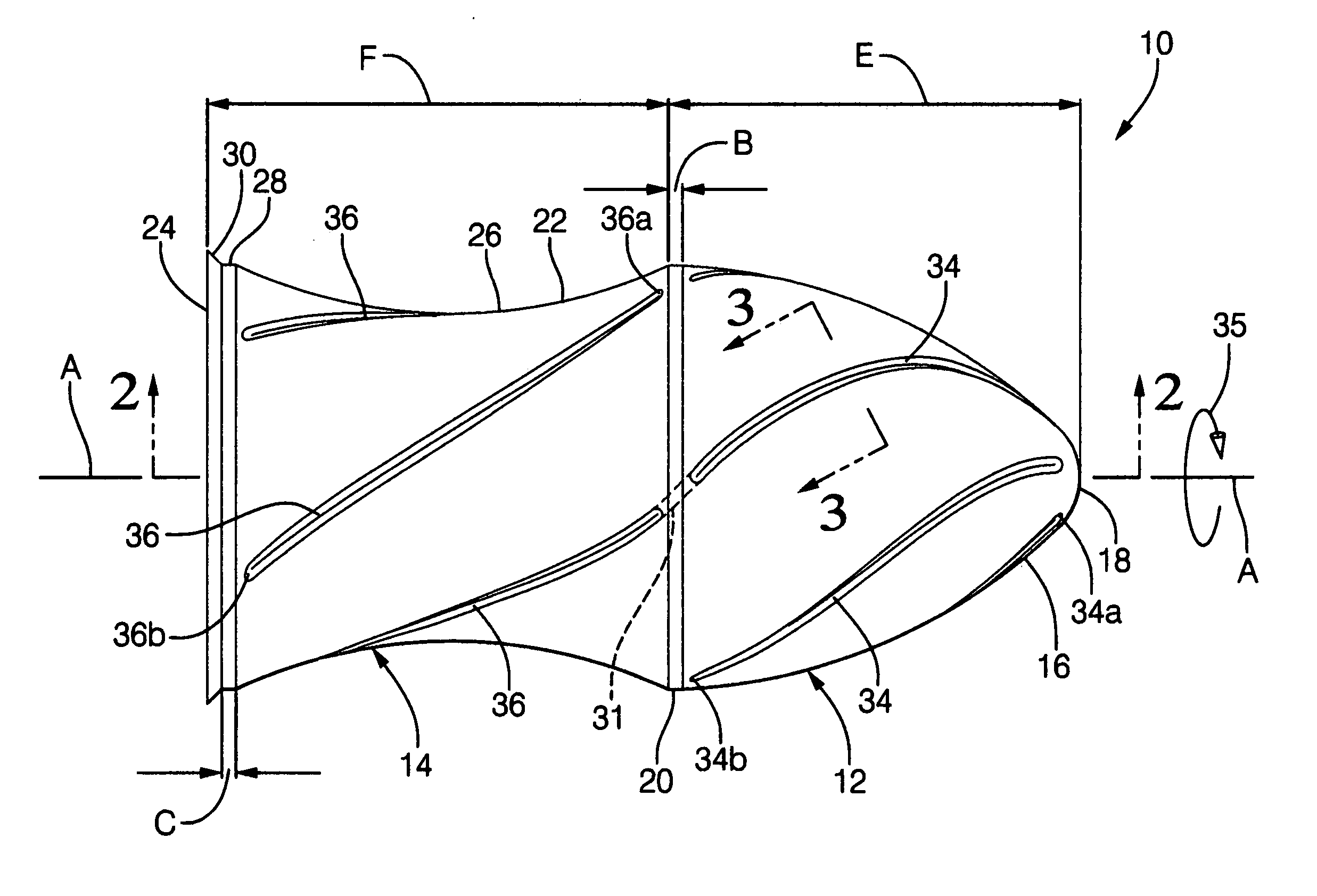
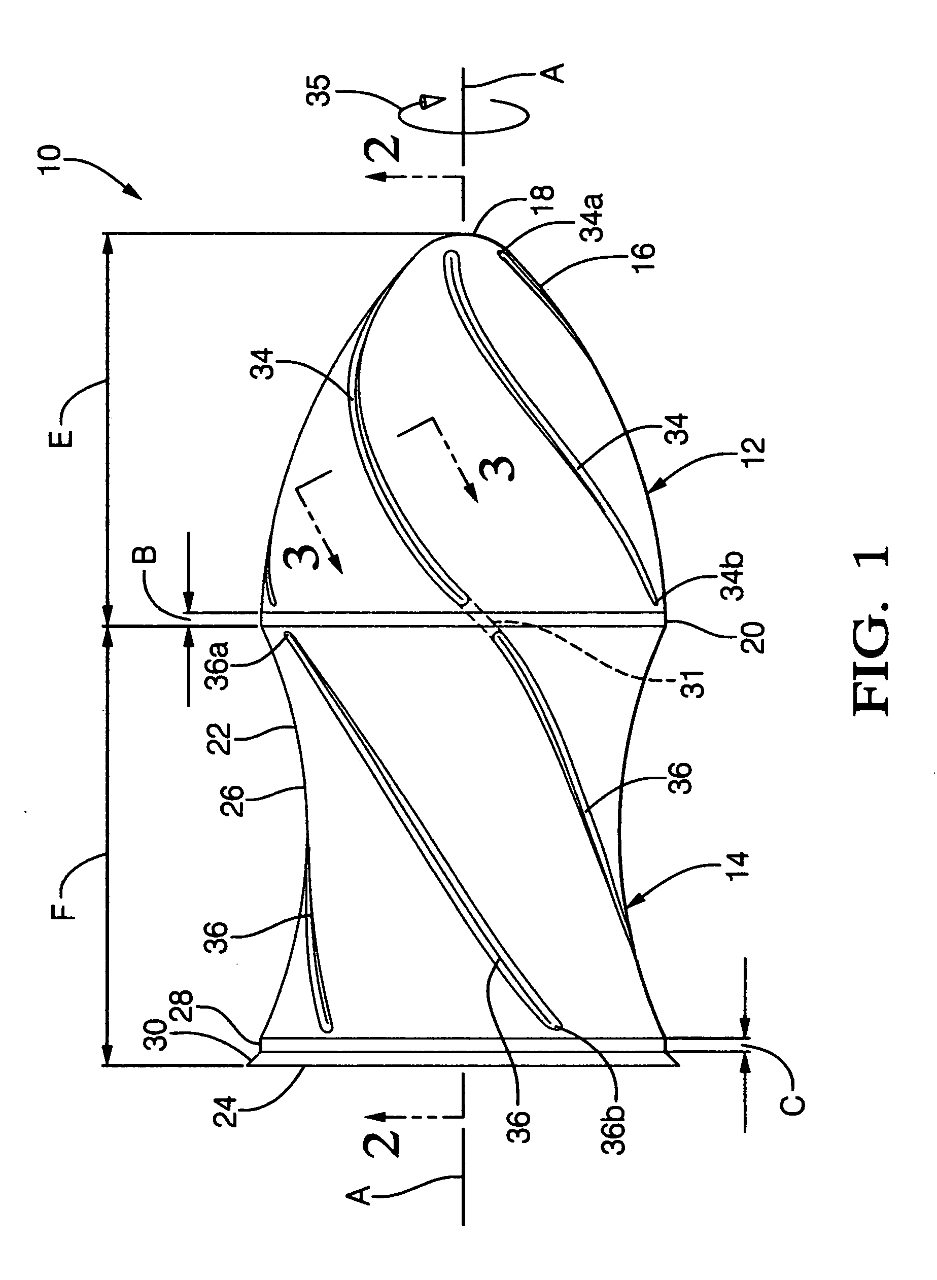
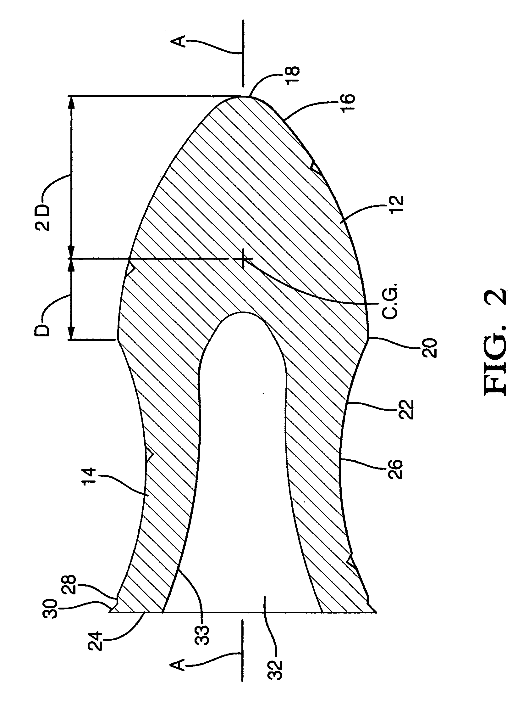
[0048] The present invention is intended for application with small caliber air powered arms such as air rifles and air hand guns, which can be of the pump type in which a charge of pressurized air is generated by a mechanism integrated into the weapon's structure adjacent its breech and is effective for powering a single shot, or, alternatively, one which employs a disposable, pre-pressurized air cylinder, which can power a number of successive shots.

[0049] Referring to FIG. 1, a pellet or projectile, indicated generally at 10, embodies the preferred embodiment of the present invention. The projectile 10 has a head portion 12 and a skirt portion 14 which are integrally formed, such as by casting, of a dense malleable material such as lead or a lead alloy. In consideration of alleged dilatory long term adverse environmental effects of lead, it is contemplated that other biodegradable, non-toxic materials can be substituted without departing from the spirit of the invention.

[0050] ...


PUM


Abstract

A projectile for an air arm is integrally formed from a single piece of dense malleable material formed as a body of revolution about a longitudinal axis having a head portion dimensioned for free sliding in the bore of an air arm and a skirt-like portion of frusto-conical form. The rearward end of the skirt portion is dimensioned to be in slight interference fit with the bore and the forward end is joined with the head portion to define a reduced diameter waist. The frustum is shell-walled, having a central recess opening to the rear and extending forwardly into the head portion. The head portion has a parabolically shaped outer surface which transitions smoothly into a hyperbolically shaped outer skirt surface for aerodynamic efficiency. Vanes are formed on the head portion to enhance in-flight spiraling rotation.

Description

RELATED PATENT APPLICATIONS [0001] The present invention claims priority to provisional application U.S. Ser. No. 60 / 667,516, filed 1 Apr. 2005, entitled “Aerodynamic Air Gun Pellet”.TECHNICAL FIELD [0002] The present invention relates to gas-propelled projectiles, such as pellets, which are intended to be expelled from air arms such as air pistols or air rifles, and particularly concerns a novel pellet configuration for achieving high muzzle velocities and superior uniformity of flight trajectory over long ranges. BACKGROUND OF THE INVENTION [0003] A projectile loaded into the barrel bore of a conventional air arm is propelled by the pressure of air which increases abruptly in the conduit leading to the breech as the piston is spring driven on release of the piston shaft. The energy stored in the spring is largely converted to work of compression performed as a nearly adiabatic process compressing the air ahead of the piston, but significantly large losses arise in the process of t...

Claims


Application Information

Patent Timeline
IPC IPC(8): F42B14/06
CPCF42B6/10F42B10/24F42B10/26
Inventor PONTIERI, JAMES
Owner PONTIERI JAMES M
Why Eureka
Try Eureka