Method and apparatus for heating mold by high frequency current

a technology of high frequency current and heating mold, which is applied in the field of methods and equipment using high frequency current, can solve the problems of temperature gradient and time delay, incomplete duplication of structure and residual stress, and increased difficulty in filling melted plastic, so as to reduce the possibility of residual stress and melting line on the product, the effect of smooth filling or enclosed, and good flow characteristics

Inactive Publication Date: 2007-04-05
JUNG TANG HUANG
View PDF4 Cites 11 Cited by
  • Summary
  • Abstract
  • Description
  • Claims
  • Application Information

AI Technical Summary

Benefits of technology

[0023] The third purpose of the current invention is to raise the mold cavity temperature to be larger than or equal to the glass transition temperature of the plastic material so that the melted plastic material will have good flow characteristic during the filling stage and the mold structure can be smoothly filled or enclosed, meanwhile, after the completion of the filling, cooling speed is set according to product need so that the occurrence possibility of residual stress and melting line on the product can be reduced and the optical quality of the product can be enhanced.
[0024] The fourth purpose of the current invention is to enhance the mold cavity temperature to above the glass transition temperature of plastic so that the thickness proportion occupied by condensation layer can be greatly reduced. During the filling stage of composite plastic material, this can avoid the separation problem between melted plastic and solid additive and better product surface quality can thus be obtained.
[0025] The fifth purpose of the current invention is, due to the raise of mold surface temperature to above the glass transition temperature of plastic, to raise mold cavity number on the mold, moreover, because melted plastic can maintain good flow characteristic during the filling stage, a better distributed filling pressure of mold cavity plastic can thus be obtained and product dimension accuracy and production stability can be enhanced.
[0026] The sixth purpose of the current invention is to bury coils in the coil guide hole within the mold, and dry cooling air can be filled into the spaces between coil and the wall of guide hole, in this way, both high frequency coil and mold cavity surface can be cooled at the same time, the users can thus select the way they want.
[0027] The seventh purpose of the current invention is to solve the very thin space problem in the mold which might lead to difficulty in the flow characteristic of plastic, therefore, sub-millimeter ultra-thin precise injection is thus possible.
[0028] The eighth purpose of the current invention is that the current device can let injection molding reach precise requirement as wafer level, a so-called wafer level plastic piece can be produced. If it can be associated with integrated circuit or MEMS device to perform wafer level packaging, many individual packaging costs can thus be saved.

Problems solved by technology

When the proportion occupied by the condensation layer is too high, the filling of melted plastic become more difficult which in turn leads to problems such as short-injection, incomplete duplication of the structure and residual stress, etc.
Since the conduction type heating could easily cause temperature gradient and time delay between heating source and the heated surface, and more seriously, the resistor could consume partial electric energy and thermal energy which could be easily released to non-heating area.
The above-mentioned inventions adopt steam heating method to heat the mold and thermal conduction is used to transfer the heat from the mold to the heated surface, however, thermal conduction could easily cause temperature gradient and time delay between heating source and surface to be heated.

Method used


Image

  • Method and apparatus for heating mold by high frequency current
  • Method and apparatus for heating mold by high frequency current
  • Method and apparatus for heating mold by high frequency current

Examples


embodiment 1

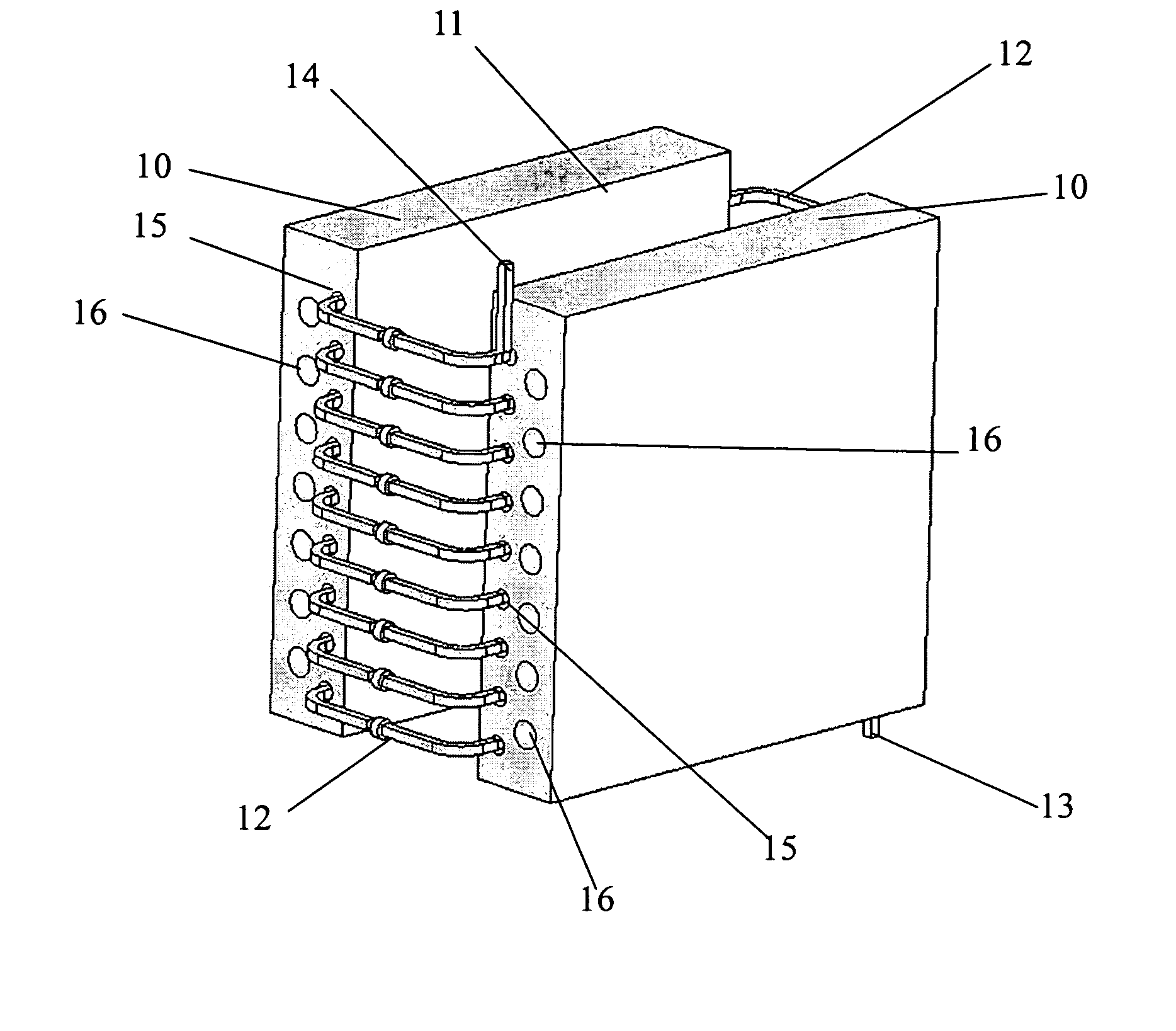
[0065] As in FIG. 13, it is an illustration of mold for hot embossing, the upper structure is hot embossing mold insert 10 having special structure surface as heating surface 11, and coil guide hole 15 is installed in the neighborhood of heating surface, coil 12 is installed inside the guide hole. Both sides of the coil are connected respectively to two coil terminal benches 23, on the terminal bench 23 are installed with terminal hole 25 and terminal connector 24 respectively, additionally, cooling hole 16 is installed on mold insert 10, which is connected to cooling liquid supply system 32 through guide tube, the hole can be introduced with cooling liquid or gas and the temperature on the heating surface 11 of mold insert 10 is controlled by the temperature and flow rate of cooling liquid.

[0066] The lower part structure in FIG. 13 is hot embossing carrier bench having an upper surface of carrier bench 35 which is used to carry thermal plastic material on and to support the downwa...

embodiment 2

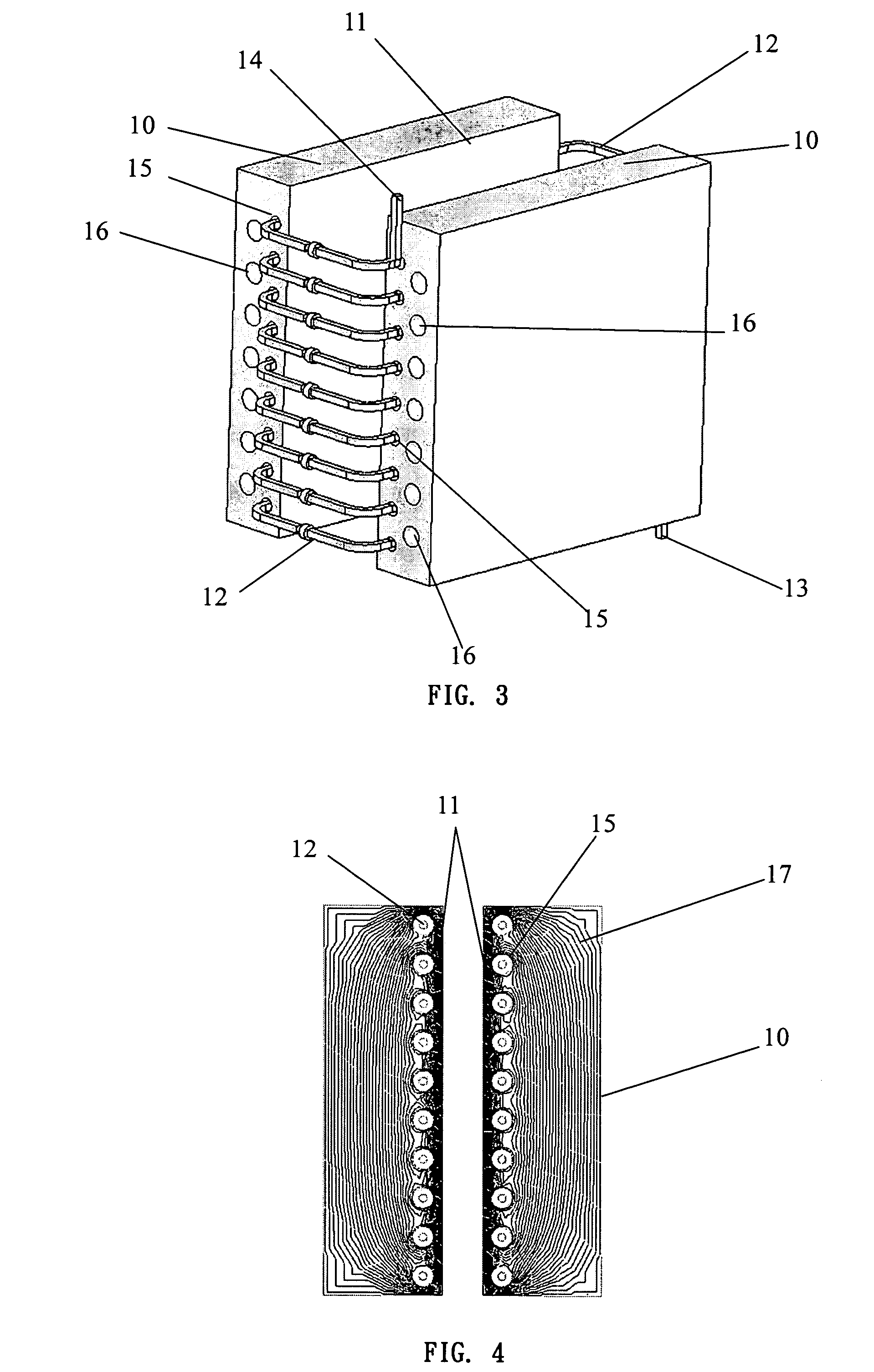
[0068] As shown in FIG. 14, it is a mold illustration for injection molding, both upper part structures are fixed and movable mold inserts 10 respectively. Both mold insert heating surfaces 11 face each other, coil guide hole 15 is installed close to heating surface and coil 12 is installed respectively inside the guide hole. Both ends of coil are connected respectively to terminal hole 25 and terminal connector 24 of terminal bench, and then the coil 12 is connected to high frequency current supply system 34.

[0069] Install cooling hole 16 on mold insert 10, connect it to cooling liquid supply system 32 through cooling pipe connector 22 and pipeline, then introduce cooling water, use the temperature and flow rate of cooling water to control the temperature of mold insert 10 and heating surface 11.

[0070] When two heating surfaces 11 get close to each other and when terminal hole 24 and terminal connector 25 on two molds get close to each other, high frequency coil will form a ring ...


PUM

PropertyMeasurementUnit
frequencyaaaaaaaaaa
frequencyaaaaaaaaaa
frequencyaaaaaaaaaa

Abstract

The method and apparatus of the invention is used to heat the surface of the mold insert or cavity by high frequency current. There are holes near the heated surface in the mold and the coils can be installed into the holes. The coils surround the heated surface and are conducted with high frequency current. Due to the directional change of the current, the blocks that are surrounded by the coils will be heated by the hysteresis losses and the eddy-current losses. The surface of the mold insert or cavity will be heated rapidly. There are cooling holes set near the heated surface or beside the coil-pipe. The cooling liquid or air can flow in the holes to carry out extra energy and the temperature of the mold will be decreased. The position of the cooling holes, the flow speed and temperature deviation of the liquid and air will influence the temperature of the mold. The method and apparatus will improve the quality of the thermal-plastic products and elevate the number of the cavity.

Description

TECHNICAL FIELD [0001] This invention relates to the means and apparatus using high frequency current to heat mold surface rapidly. More specifically it relates to build in the induction coils in the mold to heat thermal plastic materials to reduce their flow resistance and easily be filled in the mold cavity. BACKGROUND OF THE INVENTION [0002] Injection molding, injection compression molding and hot emboss forming are all processes of heating up plastics to melted state and fill them into mold cavity, then the plastics encloses specific structure of the mold and gets cooled down so as to duplicate mold structure. Generically in this invention plastics mean thermal plastic materials that can be applied in such processes include: plastic, glass, metal, composite material mainly based on plastic, glass and metal. Generally, the mold temperature is lower than the glass transition temperature of plastics, therefore, a condensation layer is created when melted plastic is in contact with ...

Claims


Application Information

Patent Timeline
Patent Type & Authority Applications(United States)
IPC IPC(8): B29C35/12
CPCB29C33/06B29C35/12B29C45/73B29C59/02B29C2035/0816
Inventor HUANG, JUNG-TANGLIN, LIANG-TSE
Owner JUNG TANG HUANG
Why Eureka
Try Eureka