Thermistor

a technology of thermistor and resistance, which is applied in the direction of resistors, varistors, current responsive resistors, etc., can solve the problems of difficulty in obtaining ptc characteristics, low initial resistance, so as to achieve easy large change in resistance, increase heat resistance in reflow step, and stable low initial resistance value

Inactive Publication Date: 2007-04-05
TDK CORPARATION
View PDF5 Cites 6 Cited by
  • Summary
  • Abstract
  • Description
  • Claims
  • Application Information

AI Technical Summary

Benefits of technology

[0009] In view of this, it is an object of the present invention to provide a thermistor with which PTC characteristics having a stably low initial resistance and a large change in resistance can be easily obtained, and furthermore heat resistance during reflow can be improved.
[0011] With the thermistor according to the first invention, since the conductor plates that electrically connect the pair of electrodes are fixed to the inner faces of the pair of substrates and are disposed so as to be at least partially overlapping, a stably low initial resistance value is easily obtained as the initial resistance value between the pair of electrodes. If an electric current between the pair of electrodes generates joule heat so that the matrix resin heats up to a specific temperature and greatly expands thermally, the conductor plates will move apart, and this instantly cuts off the electrical connection between the pair of electrodes. Accordingly, there is a sharp increase in the electrical resistance between the pair of electrodes, and PTC characteristics with a large change in resistance can be easily obtained.
[0013] With the thermistor according to the second invention, since the pair of conductor plates that electrically connect the pair of electrodes are in contact with each other in their initial state, a stably low initial resistance value is easily obtained as the initial resistance value between the pair of electrodes. If an electrical current between the pair of electrodes generates joule heat so that the matrix resin heats up to a specific temperature and greatly expands thermally, the pair of conductor plates will move apart, and this instantly cuts off the electrical connection between the pair of electrodes. Accordingly, there is a sharp increase in the electrical resistance between the pair of electrodes, and PTC characteristics with a large change in resistance can be easily obtained.
[0016] With the thermistor according to the first invention, since the conductor plates that electrically connect the pair of electrodes are fixed to the inner faces of the pair of substrates and are disposed so as to be at least partially overlapping, a stably low initial resistance value can be easily obtained as the initial resistance value between the pair of electrodes. If an electrical current between the pair of electrodes generates joule heat so that the matrix resin heats up to a specific temperature and greatly expands thermally, the conductor plates will move apart, and this instantly cuts off the electrical connection between the pair of electrodes, so PTC characteristics with a large change in resistance can be easily obtained. Because no conductive filler with a small coefficient of linear expansion that would decrease the thermal expansion of the matrix resin is mixed into this resin, heat resistance in a reflow step can be increased by using a matrix resin with higher heat resistance.
[0017] With the thermistor according to the second invention, since the pair of conductor plates that electrically connect the pair of electrodes are in contact with each other in their initial state, a stably low initial resistance value is easily obtained as the initial resistance value between the pair of electrodes. If an electrical current between the pair of electrodes causes the matrix resin to heat up to a specific temperature and greatly expand thermally, the pair of conductor plates will move apart, and this instantly cuts off the electrical connection between the pair of electrodes, so PTC characteristics with a large change in resistance can be easily obtained. Because no conductive filler with a small coefficient of linear expansion that would decrease the thermal expansion of the matrix resin is mixed into this resin, heat resistance in a reflow step can be increased by using a matrix resin with higher heat resistance.

Problems solved by technology

With the conventional thermistor described in Japanese Laid-Open Patent Application 2000-82604, the PTC characteristics and the initial resistance between the pair of electrodes vary greatly with the shape, added amount, dispersion state, and so forth of the conductive filler mixed into the matrix resin, and this makes it difficult to obtain PTC characteristics with a stably low initial resistance and a large change in resistance.
Nevertheless, because resin materials with a large coefficient of linear expansion generally have low heat resistance, defects in a reflow step in which the thermistor is mounted to a substrate surface may occur frequently.

Method used


Image

  • Thermistor
  • Thermistor
  • Thermistor

Examples


example 1

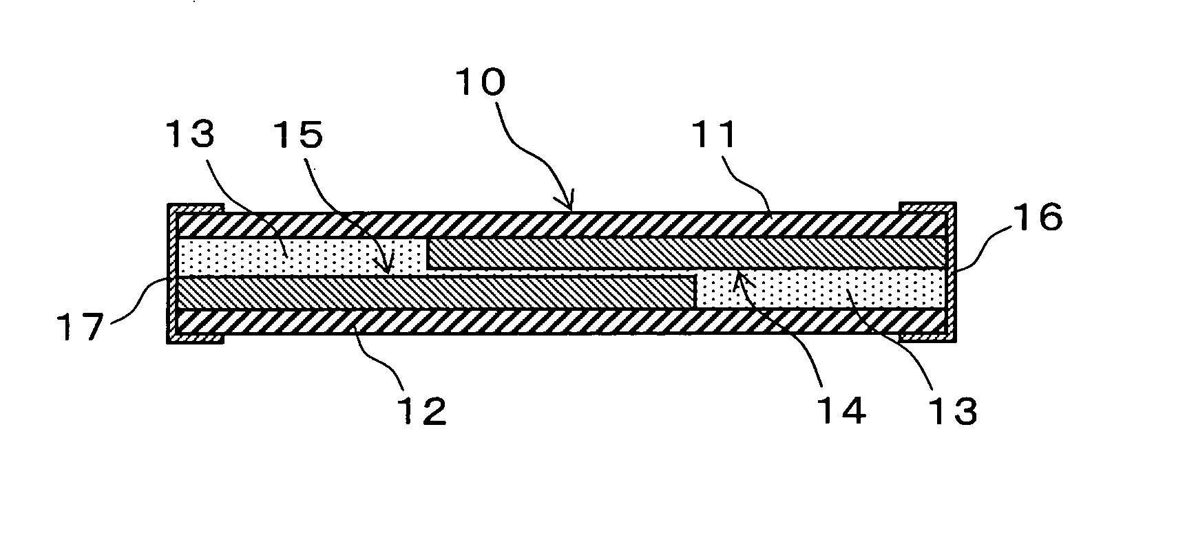
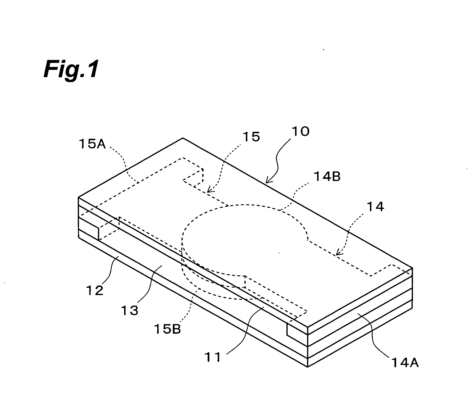
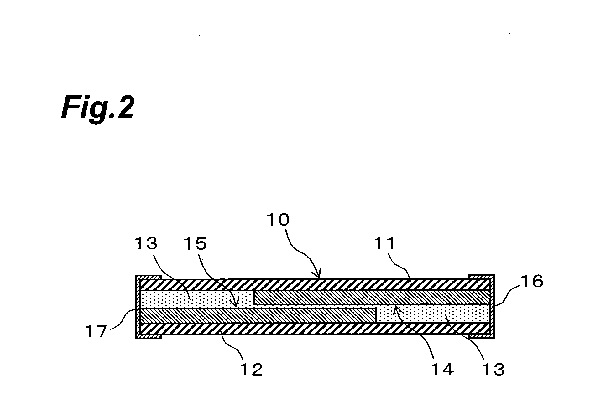
[0057] As Example 1, a thermistor having a structure illustrated in FIGS. 1 and 2 was manufactured, and the initial resistance (mΩ) at 25° C. between the electrode 16 and electrode 17 thereof, the change in resistance (log 10), the resin glass transition point (° C.) / DMA, and the resistance (mΩ) after reflow at 260° C. were measured.

[0058] The upper substrate 11 and the lower substrate 12 of the thermistor 10 in Example 1 were hot-molded for 2 hours at a temperature of 180° C. in a 3 MPa vacuum press. The matrix resin layer 13 was prepared by blending an epoxy resin (trade name E4080, an epoxy resin with an epoxy equivalent of 167 g, made by Asahi Chemical Industries) and a flexible epoxy resin (trade name E4005, a flexible epoxy resin with an epoxy equivalent of 510 g, made by Asahi Chemical Industries) in a weight ratio of 2 / 1, and then adding an equivalent amount of methyltetrahydrophthalic anhydride (trade name B570, a curing agent with an acid anhydride equivalent of 160 g, ma...


PUM


Abstract

A thermistor comprising a pair of substrates; conductor plates for electrically connecting a pair of electrodes, the conductor plates being fixed on inner faces of the pair of substrates respectively; and a matrix resin layer disposed between the pair of substrates; wherein the conductor plates are disposed so as to be at least partially overlapping.

Description

BACKGROUND OF THE INVENTION [0001] 1. Field of the Invention [0002] The present invention relates to a thermistor (P-PTC) having so-called PTC (Positive Temperature Coefficient) characteristics. [0003] 2. Related Background Art [0004] A characteristic of a thermistor having organic positive characteristics (P-PTC) is that its electrical resistance increases sharply as the temperature rises within a specific temperature region, that is, it has PTC (Positive Temperature Coefficient) characteristics, and these thermistors have been used in battery pack protection elements for various kinds of portable device, as well as in temperature fuses, temperature switches, and so forth. [0005] One thermistor of this type that has been commonly known up to now is produced by mixing nickel powder, carbon black, or another such conductive filler into a matrix resin composed of a thermoplastic resin or thermosetting resin, molding this in the form of a plate or block, and providing this product with...

Claims


Application Information

Patent Timeline
Patent Type & Authority Applications(United States)
IPC IPC(8): H01C7/13
CPCH01C1/14H01C7/008H01C7/021H01C7/13
Inventor SUGIYAMA, TSUYOSHI
Owner TDK CORPARATION
Why Eureka
Try Eureka