

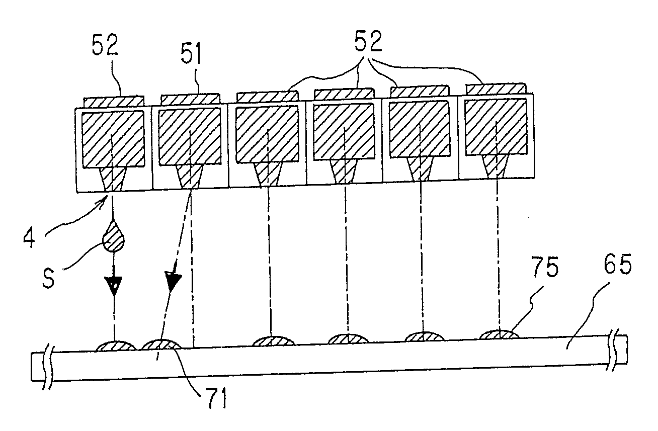
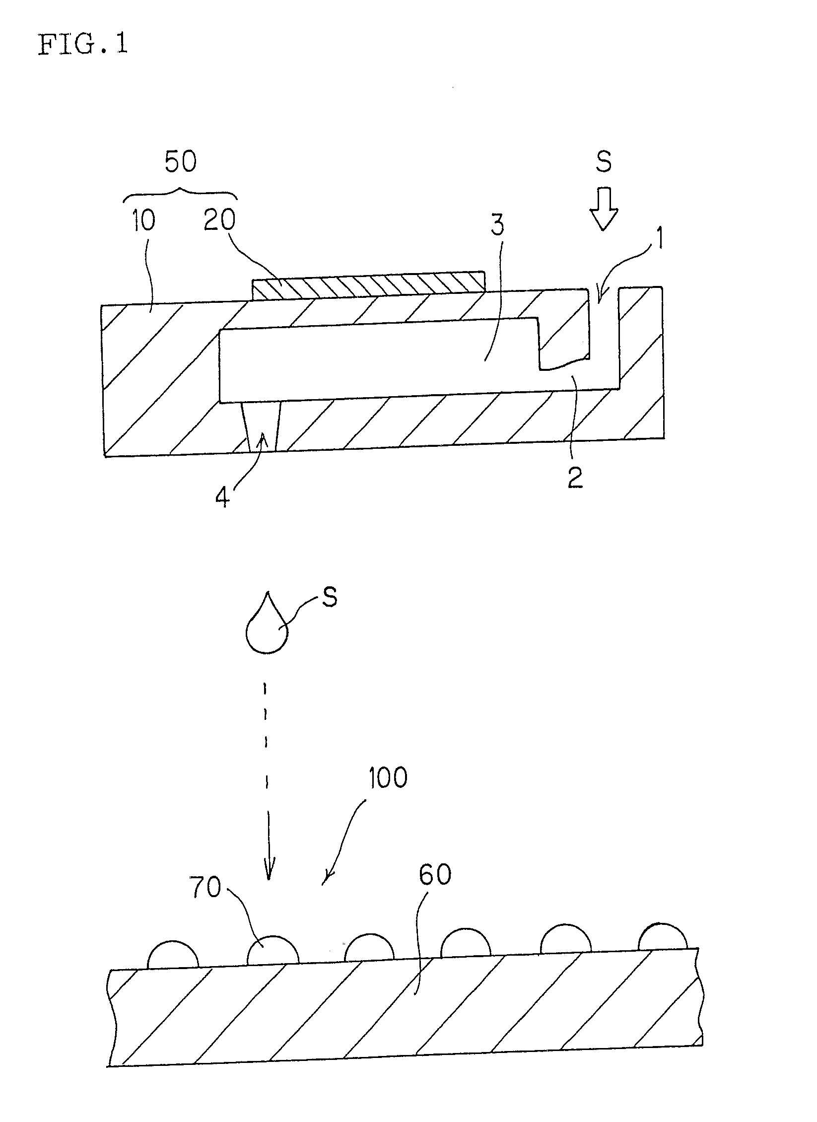
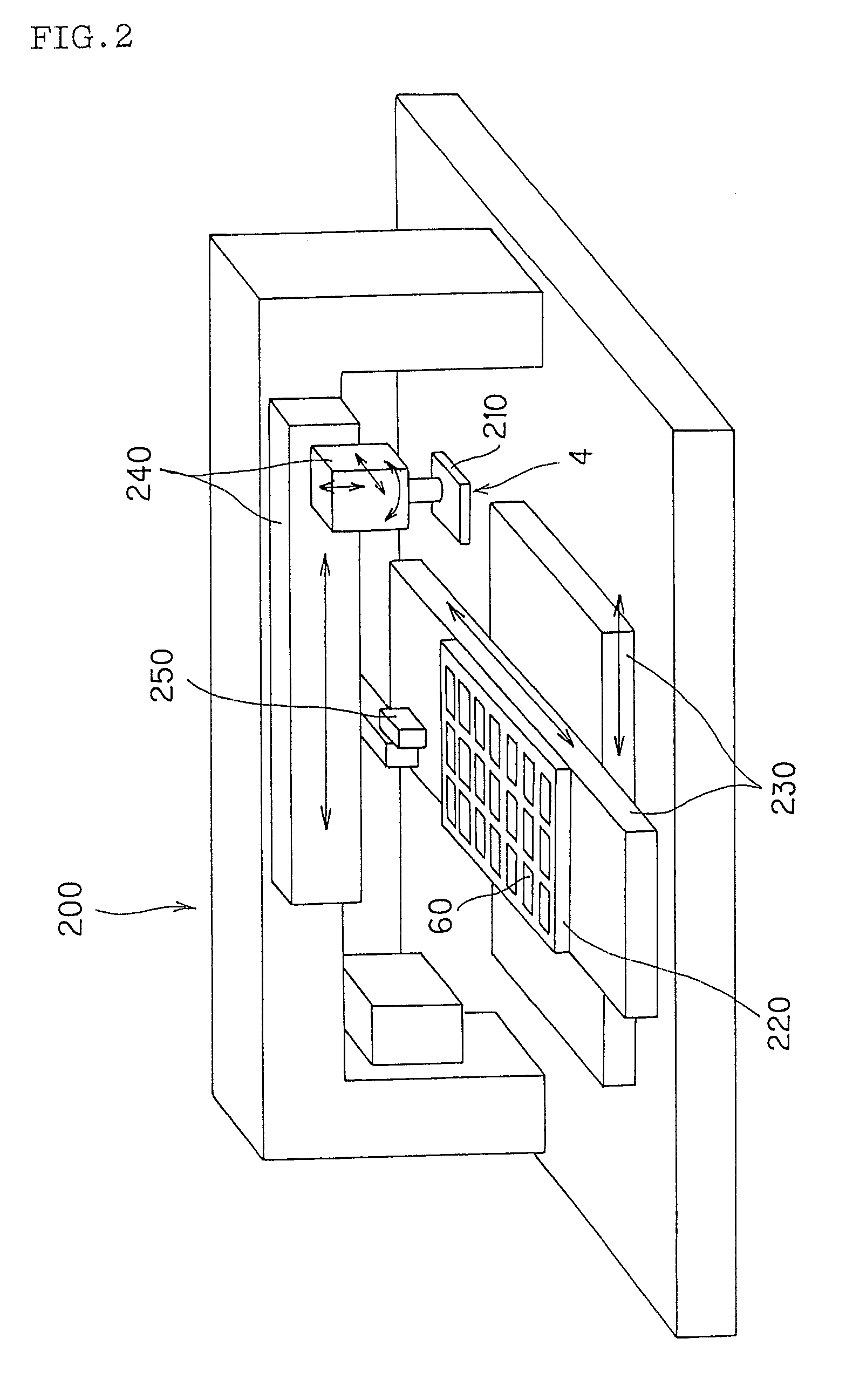
Method of producing microarray
a microarray and microarray technology, applied in the field of microarray production, can solve the problems of poor discharge conditions and decrease the working efficiency, and achieve the effects of high density, high precision and stable formation
- Summary
- Abstract
- Description
- Claims
- Application Information
AI Technical Summary
Benefits of technology
Problems solved by technology
Method used
Image

Examples
example 1
[0097] The microarray of EXAMPLE 1 was produced using the following procedures (1) to (5) under the following condition (A).
[Condition (A)]
[0098] Number of discharge holes per head: 96[0099] Kinds of liquid samples: 96[0100] Liquid sample: c-DNA solution dissolved in 10 mM of phosphate buffer (containing0.1 μg / μL of c-DNA) [0101] Carrier: Poly-L-lysine (PLL) coated slide glass, having a size of 76 mm×26 mm×1 mm (thick) [0102] Spot pattern: 12 rows×8 columns, 0.3 mm pitch, spot diameter 120 μm [0103] Number of microarrays produced: 400 [0104] Number of trays: 20 (20 trays each having 20 carriers were used)
[Procedures (1) to (5)][0105] (1) Before the liquid sample was practically spotted on a carrier on the first tray and a carrier on the next tray, step (A) was conducted. Specifically, the liquid sample discharged from the outlet to outside was experimentally ejected onto an inspection carrier to form inspection spots. The resultant inspection spots were inspected for their quali...
example 2
[0110] The procedures of EXAMPLE 1 were essentially repeated except that in the procedure (2) the formation of the defective spots was stopped by stopping the transmittance of the electrical signal for driving the piezoelectric / electrostrictive element of the defective discharge unit that provided the defective spots instead of the following: The formation of the defective sample spots was stopped conveniently by inserting a pipette or the like from the inlet of the discharge unit of interest, and aspirating the liquid to completely draw out the liquid sample. Then, 200 μl of pure water was injected from the inlet, the outlet was vacuum-aspirated, and the injection and the aspiration were repeated to clean the defective discharge unit(s)
example 3
[0125] The microarray of EXAMPLE 3 was produced using the following procedures (1) to (13) under the following condition (B)
[Condition (B)]
[0126] Number of discharge holes per head: 96 [0127] Kinds of liquid samples: 960 [0128] Liquid sample: c-DNA solution dissolved in 25 mM of TE buffer (containing 0.2 μg / μL of c-DNA) [0129] Carrier: Poly-L-lysine (PLL) coated slide glass, having a size of 76 mm×26 mm×1 mm (thick) [0130] Spot pattern: 12 rows×8 columns, 0.3 mm pitch, spot diameter 120 μm [0131] Number of microarrays produced: 800 [0132] Number of trays: 40 (one tray each having 20 carriers were used)
[Procedures (1) to (13)][0133] (1) The first head containing first 96 types of c-DNAs among 960 types was subjected to step (A). Specifically, the liquid sample discharged from the outlet to outside was experimentally ejected onto an inspection carrier to form inspection spots. The resultant inspection spots were inspected for their quality to determine whether the inspected spots ...
PUM
 Abstract
Description
Claims
Application Information