
Method of producing microarray

a microarray and microarray technology, applied in the field of microarray production, can solve the problems of poor discharge conditions and decrease the working efficiency, and achieve the effects of high density, high precision and stable formation

Inactive Publication Date: 2010-02-23
NGK INSULATORS LTD
View PDF16 Cites 4 Cited by
  • Summary
  • Abstract
  • Description
  • Claims
  • Application Information

AI Technical Summary

Benefits of technology

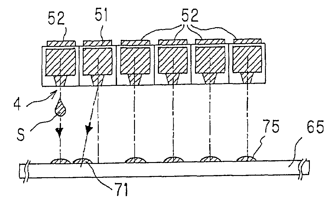
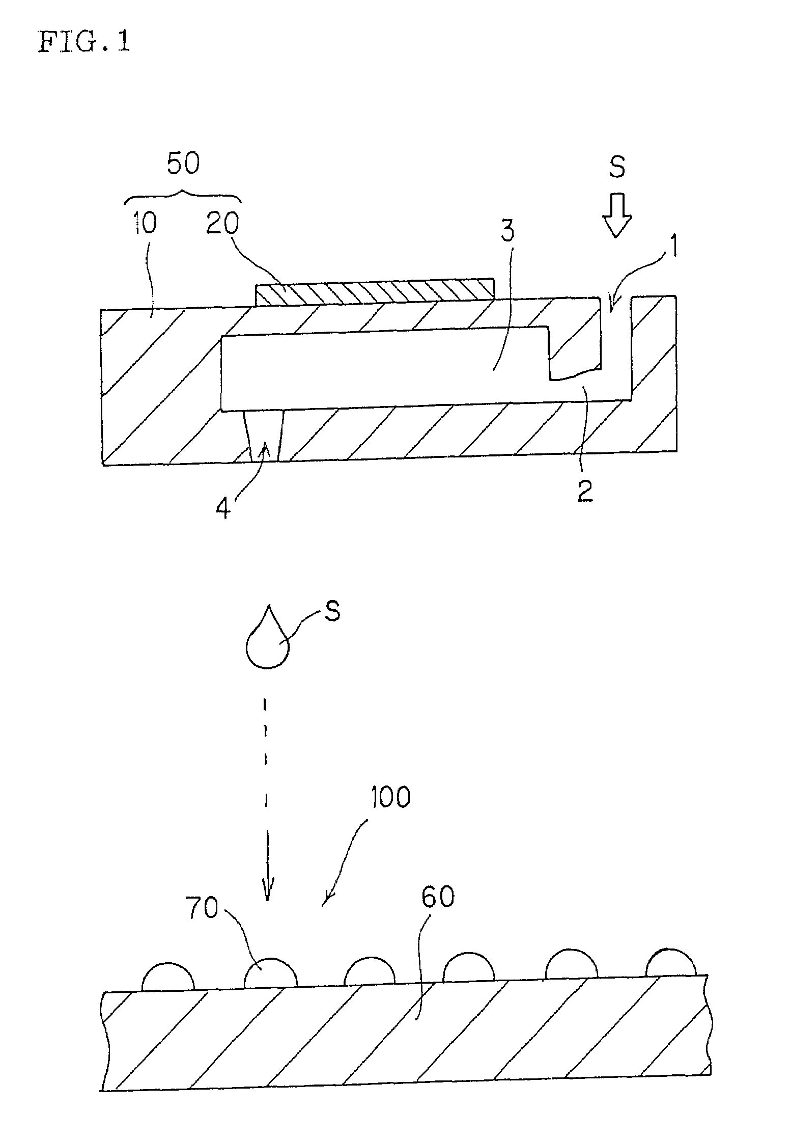
[0007][1] A first aspect of the present invention provides a method of producing a microarray including sample spots on a carrier in a predetermined pattern by providing a plurality of discharge units each including a substrate having an inlet, a channel, a reservoir, and an outlet of a liquid sample, and a piezoelectric / electrostrictive element disposed at a position corresponding to the reservoir on the substrate; and by ejecting a liquid sample discharged from the outlet to outside onto the carrier to form the sample spots corresponding to each discharge unit on the carrier, the method comprising the steps of: (A) ejecting the liquid sample discharged from the outlet to outside onto an inspection carrier to form inspection spots, inspecting the resultant inspection spots for their quality to determine whether the inspected spots are defective or successful, and detecting the defective discharge unit; (B) making the detected defective discharge unit stop discharging the liquid sample from the outlet to outside, to prevent the formation of a defective sample spot from the defective discharge unit; (C) forming successful sample spots on the carrier using successful discharge units excluding the defective discharge units to provide a successful microarray on which the successful spots are aligned in a predetermined pattern on the carrier; and (D) forming a successful spot to be formed originally on the successful microarray at the position of the defective spot where no spot is formed in step (B), thereby providing a finished microarray including the successful spots aligned on the carrier in a predetermined pattern.
[0023]According to the present invention, there can be provided a microarray having spots that are formed stably with high precision and high density and having decreased defective spots that is used for high-definition, high-speed analysis, when the microarray is produced by ejecting drops of a small volume liquid sample onto a predetermined carrier or support to form small sample spots aligned and immobilized with high density on a carrier or a base.

Problems solved by technology

In these methods, the production of the defective spots during recovery causes a problem.
It is believed that one of the causes of defective spots is poor conditions of the discharge.
In addition, the determination of the defective discharge unit from which the defective spots are produced requires much time and effort, thereby decreasing the working efficiency.

Method used


Image

  • Method of producing microarray
  • Method of producing microarray
  • Method of producing microarray

Examples


example 1

[0067]The microarray of EXAMPLE 1 was produced using the following procedures (1) to (5) under the following condition (A).

[Condition (A)]

[0068]Number of discharge holes per head: 96[0069]Kinds of liquid samples: 96[0070]Liquid sample: c-DNA solution dissolved in 10 mM of phosphate buffer (containing 0.1 μg / μL of c-DNA)[0071]Carrier: Poly-L-lysine (PLL) coated slide glass, having a size of 76 mm×26 mm×1 mm (thick)[0072]Spot pattern: 12 rows×8 columns, 0.3 mm pitch, spot diameter 120 μm[0073]Number of microarrays produced: 400[0074]Number of trays: 20 (20 trays each having 20 carriers were used)

[Procedures (1) to (5)][0075](1) Before the liquid sample was practically spotted on a carrier on the first tray and a carrier on the next tray, step (A) was conducted. Specifically, the liquid sample discharged from the outlet to outside was experimentally ejected onto an inspection carrier to form inspection spots. The resultant inspection spots were inspected for their quality to determine ...

example 2

[0080]The procedures of EXAMPLE 1 were essentially repeated except that in the procedure (2) the formation of the defective spots was stopped by stopping the transmittance of the electrical signal for driving the piezoelectric / electrostrictive element of the defective discharge unit that provided the defective spots instead of the following: The formation of the defective sample spots was stopped conveniently by inserting a pipette or the like from the inlet of the discharge unit of interest, and aspirating the liquid to completely draw out the liquid sample. Then, 200 μl of pure water was injected from the inlet, the outlet was vacuum-aspirated, and the injection and the aspiration were repeated to clean the defective discharge unit(s)

example 3

[0096]The microarray of EXAMPLE 3 was produced using the following procedures (1) to (13) under the following condition (B)

[Condition (B)]

[0097]Number of discharge holes per head: 96[0098]Kinds of liquid samples: 960[0099]Liquid sample: c-DNA solution dissolved in 25 mM of TE buffer (containing 0.2 μg / μL of c-DNA)[0100]Carrier: Poly-L-lysine (PLL) coated slide glass, having a size of 76 mm×26 mm×1 mm (thick)[0101]Spot pattern: 12 rows×8 columns, 0.3 mm pitch, spot diameter 120 μm[0102]Number of microarrays produced: 800[0103]Number of trays: 40 (one tray each having 20 carriers were used)

[Procedures (1) to (13)][0104](1) The first head containing first 96 types of c-DNAs among 960 types was subjected to step (A). Specifically, the liquid sample discharged from the outlet to outside was experimentally ejected onto an inspection carrier to form inspection spots. The resultant inspection spots were inspected for their quality to determine whether the inspected spots were defective or s...


PUM

PropertyMeasurementUnit
distanceaaaaaaaaaa
distanceaaaaaaaaaa
humidityaaaaaaaaaa

Abstract

A method of producing a microarray including: (A) ejecting a liquid sample from an outlet onto an inspection carrier to form inspection spots, inspecting the resultant inspection spots for their quality to determine whether the inspected spots are defective or successful, and detecting a defective discharge unit, if any; (B) making the detected defective discharge unit stop discharging the liquid sample to prevent formation of the defective sample spot; (C) forming successful sample spots on a carrier using successful discharge units to provide a successful microarray on which the successful spots are aligned in a predetermined pattern on the carrier; and (D) forming a successful spot to be formed originally on the successful microarray at the position of the defective spot where no spot is formed in step (B).

Description

TECHNICAL FIELD[0001]The present invention relates to a method of producing a microarray, including biochips and the like. More particularly, the present invention relates to a method of producing a microarray having spots that are formed stably with high precision and high density and having fewer defective spots that is used for high-definition, high-speed analysis. Such a microarray is produced by ejecting drops of a small volume of liquid sample onto a predetermined carrier or base to form small sample spots aligned and immobilized with high density on the carrier or the base.BACKGROUND ART[0002]Analysis of a gene structure has progressed remarkably in recent years. A number of gene structures including human genes have been revealed. For the analysis of a gene structure, a DNA microarray including biochips is used, where a solution containing thousands to millions of different DNA strands are aligned and immobilized as microspots on a carrier or a base such as a slide glass.[00...

Claims


Application Information

Patent Timeline
Patent Type & Authority Patents(United States)
IPC IPC(8): H01J49/00C12Q1/68G01N35/10B01J19/00B01L3/02C40B40/06C40B40/10C40B40/14C40B60/14
CPCB01J19/0046B01L3/0268B01J2219/00378B01J2219/00529B01J2219/00533B01J2219/00585B01J2219/00596B01J2219/00605B01J2219/00612B01J2219/00628B01J2219/00637B01J2219/00659B01J2219/00662B01J2219/00677B01J2219/00693B01J2219/00722B01J2219/00725B01J2219/0074B01L2200/143B01L2400/0439C40B40/06C40B40/10C40B40/14C40B60/14G01N2035/1041
Inventor NORITAKE, MOTOOOHNISHI, TAKAOHIROTA, TOSHIKAZU
Owner NGK INSULATORS LTD
Learn More