Photodetector having a near field concentration

a near field concentration and photodetector technology, applied in the field of photodetectors, can solve the problem that the solution is not applicable per se to the matrix of detectors, and achieve the effect of concentrating light energy and improving the detectivity of the detector

Inactive Publication Date: 2007-04-19
SOFRADIR
View PDF18 Cites 18 Cited by
  • Summary
  • Abstract
  • Description
  • Claims
  • Application Information

AI Technical Summary

Benefits of technology

[0007] It is an object of the invention to concentrate the light energy on a reduced surface of the detector by exploiting near field localization phenomena and the properties of certain surface waves known as

Problems solved by technology

This solution is not applicable

Method used


Image

  • Photodetector having a near field concentration
  • Photodetector having a near field concentration
  • Photodetector having a near field concentration

Examples


first embodiment

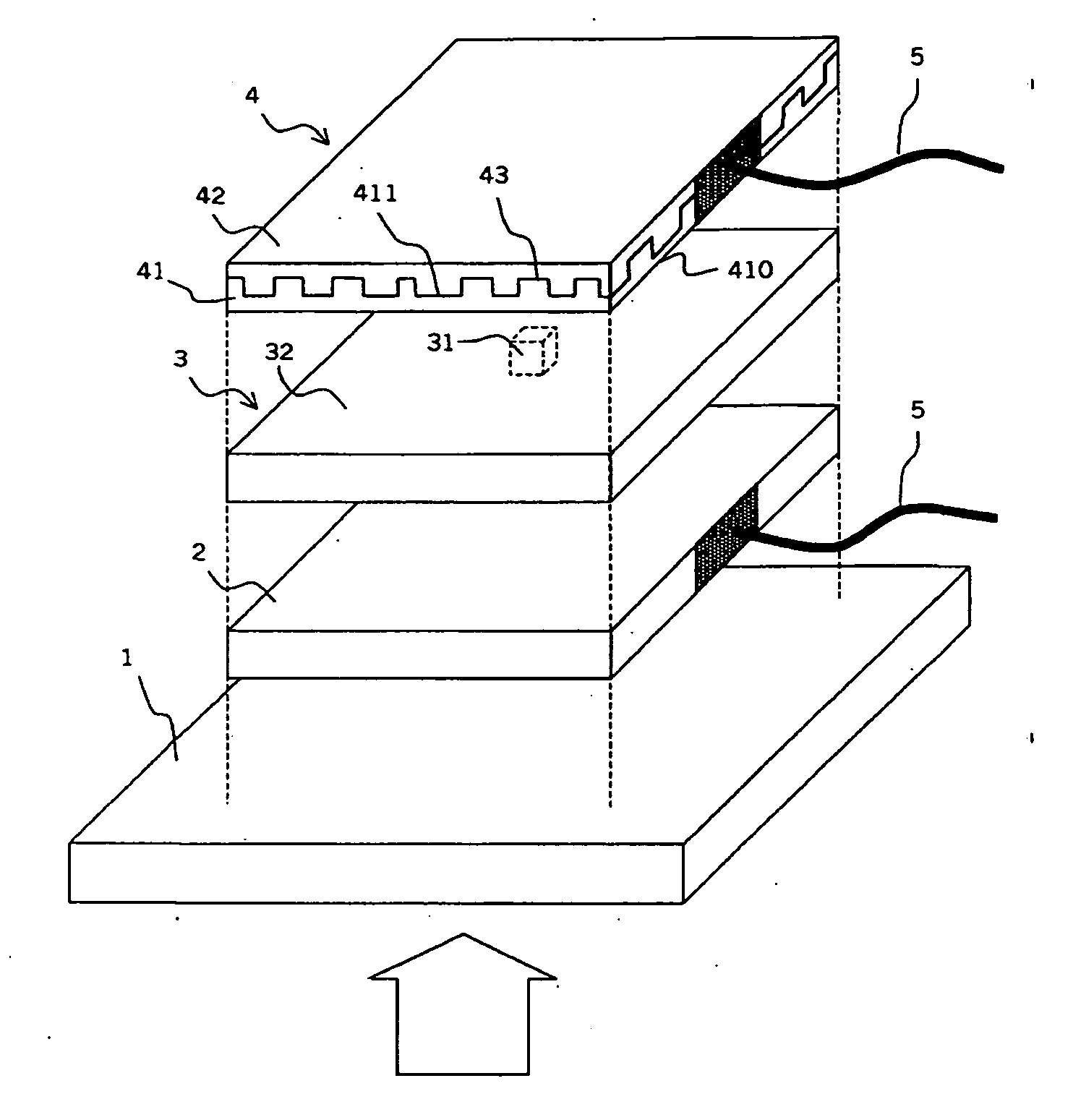
[0080] In a first embodiment, illustrated in FIG. 17, the layer 41 constituting the structure is made from an isotropic dielectric material, the profile of each groove along the axis perpendicular to the direction of the groups being composed of mutually parallel plane facets with different heights according to a profile of the same type as those in FIGS. 15 and 16. It has a protective layer 42 on top.

second embodiment

[0081] In a second embodiment, illustrated in FIG. 18, the layer 41 constituting the structure is made from a material composed of mutually parallel alternate layers 412, 413 of equal thickness and a central layer of double thickness corresponding to the defect, said layers alternately comprising a first material having a first permittivity and a second material having a second permittivity, the plane of the layers being perpendicular to the plane of the lower face and the profile of each groove along the axis perpendicular to the direction of the grooves being composed of regular crenellations with a pitch two times greater than the thickness of the alternate layers. This arrangement makes it possible to simplify considerably the profile of the upper face of the grating, which now comprises only two different heights. The incident beam is represented by a thick arrow in these two FIGS. 17 and 18.

[0082] For example, let there be a metallic structure of the same type as that represen...


PUM


Abstract

The field of the invention is that of photodetectors (10), and more precisely so-called quantum well photodetectors operating in the medium infrared, known by the acronym QWIP standing for Quantum Well Infrared Photodetector.
It is an object of the invention to increase the detectivity of the detectors by significantly reducing the surface area of the detection zone while conserving the incident flux. This result is obtained by arranging a structure (4) or grating on the active zone (31) of the photodetector (10), which couples the incident wave and confines it on the active zone (31).
The major features of this structure (4) or this grating are that it comprises patterns or grooves having a first spatial frequency and a second spatial frequency, and also comprising a central defect.

Description

CROSS-REFERENCE TO RELATED APPLICATIONS [0001] The present Application is based on International Application No. PCT / EP2004 / 053324, filed on Dec. 7, 2004, which in turn corresponds to FR 03 / 14717 filed on Dec. 16, 2003, and priority is hereby claimed under 35 USC §119 based on these applications. Each of these applications are hereby incorporated by reference in their entirety into the present application.BACKGROUND OF THE INVENTION [0002] 1. Field of the Invention [0003] The field of the invention is that of photodetectors, and more precisely so-called quantum well photodetectors operating in the medium infrared, known by the acronym QWIP standing for Quantum Well Infrared Photodetector. [0004] 2. Description of the Prior Art [0005] In order to improve the performance of the detectors it is necessary to optimize their detectivity, i.e. the ratio between the response of the detector and the noise. When the electronic noise is negligible, the total noise is proportional to the square...

Claims


Application Information

Patent Timeline
IPC IPC(8): H01L31/113H01L31/0236H01L31/0352
CPCH01L31/0236H01L31/0352Y02E10/50
Inventor DE ROSSI, ALFREDOCARRAS, MATHIEUBOIS, PHILIPPE
Owner SOFRADIR
Why Eureka
Try Eureka