

Printed wiring board and method of suppressing power supply noise thereof
Patent Information
- Authority / Receiving Office
- US · United States
- Current Assignee / Owner
- NEC CORP
- Publication Date
- 2007-04-19
Smart Images
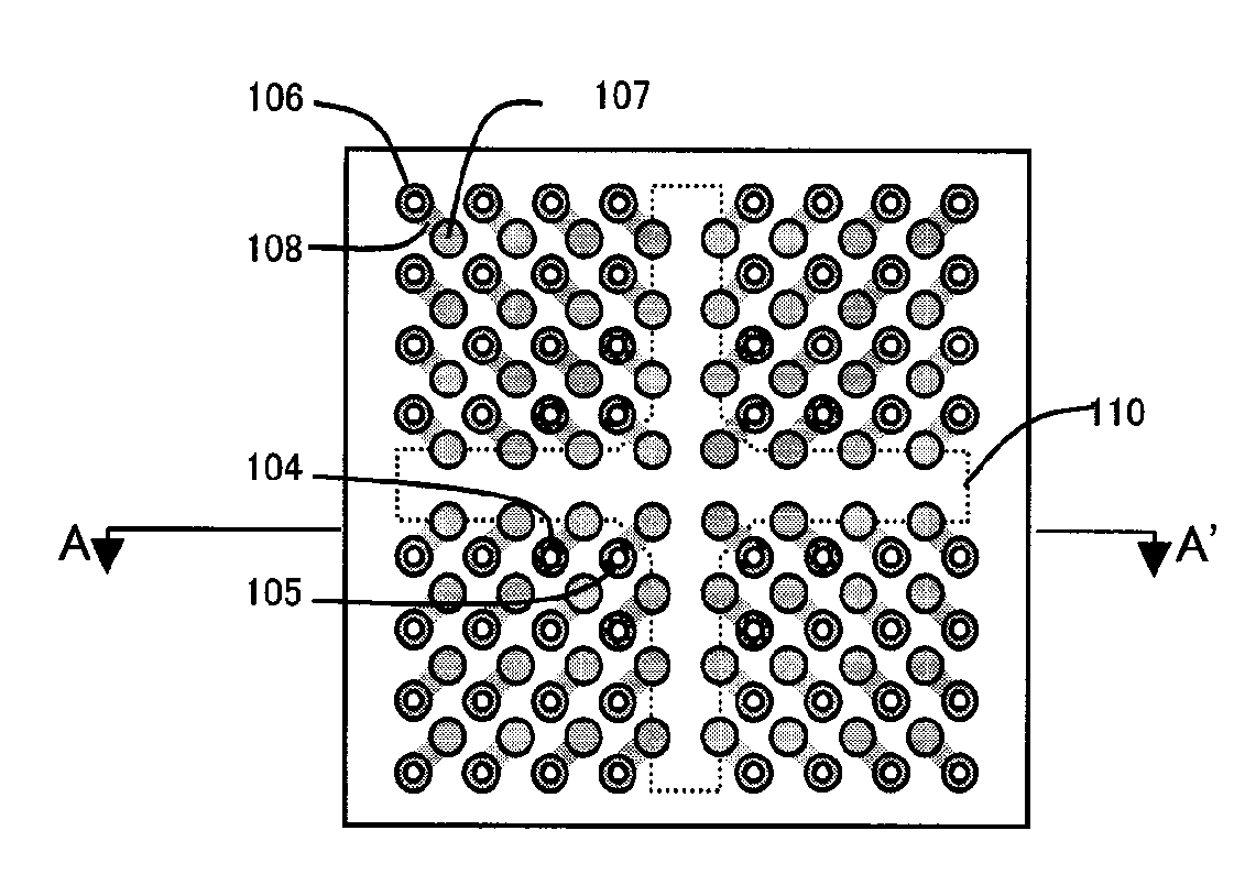
Figure 1 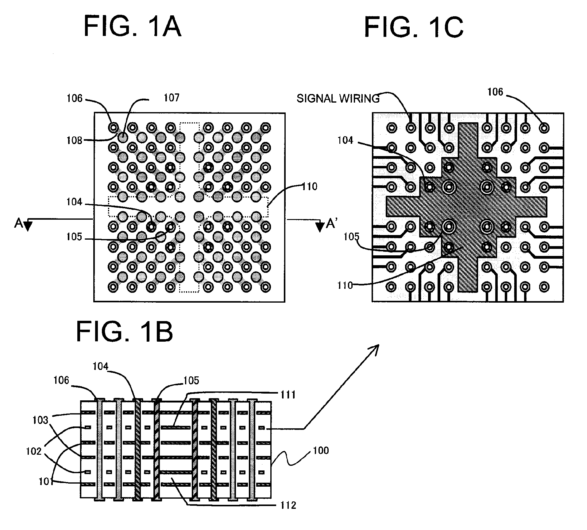
Figure 2 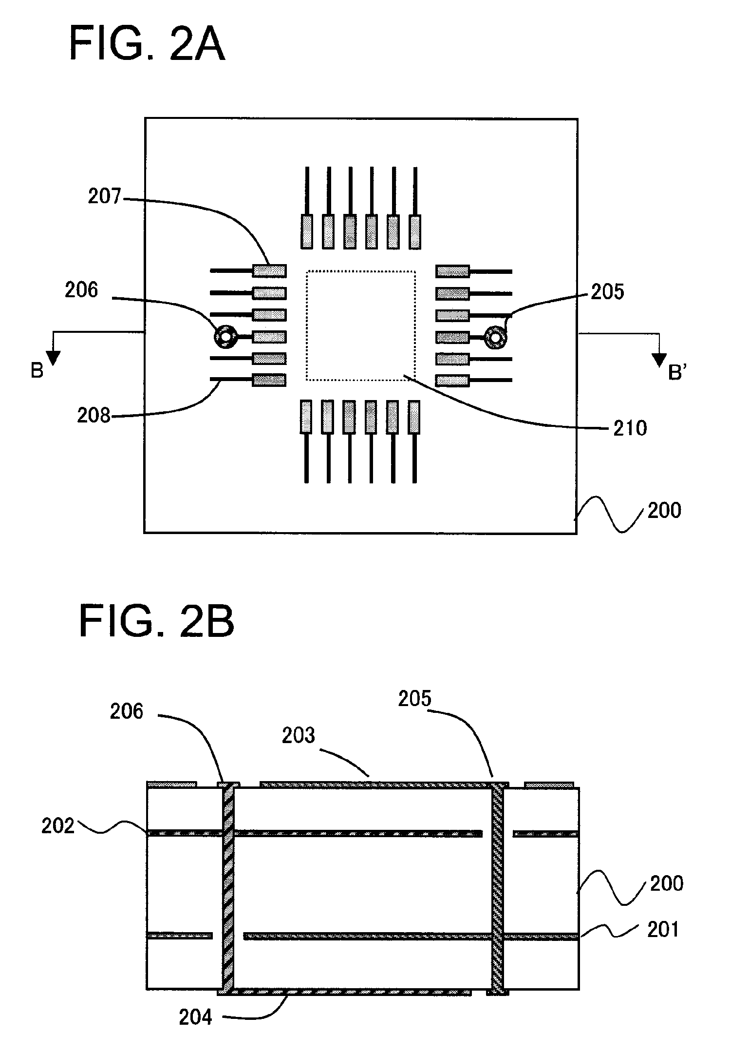
Figure 3
Abstract
Description
FIELD OF THE INVENTION
[0001] The present invention relates to a printed wiring board and a method of suppressing power supply noise thereof. BACKGROUND OF THE INVENTION
[0002] Since a large amount of data is processed in electronic devices such as a communication device, a server, and a PC (personal computer), an operating frequency and a signal transfer rate of the electronic devices have risen. For this reason, power supply noise has also increased, so that a problem due to the power supply noise has also arisen. It is thus necessary to suppress the power supply noise to stabilize an operation of a product and to improve quality of the product.
[0003] Conventionally, a capacitor for absorbing the power supply noise from a semiconductor device (IC) and stabilizing an operation of the semiconductor device (IC) has been mounted around the IC. However, as the operation of the semiconductor device has become faster in recent years, a problem in which the capacitor does not serve as a ...