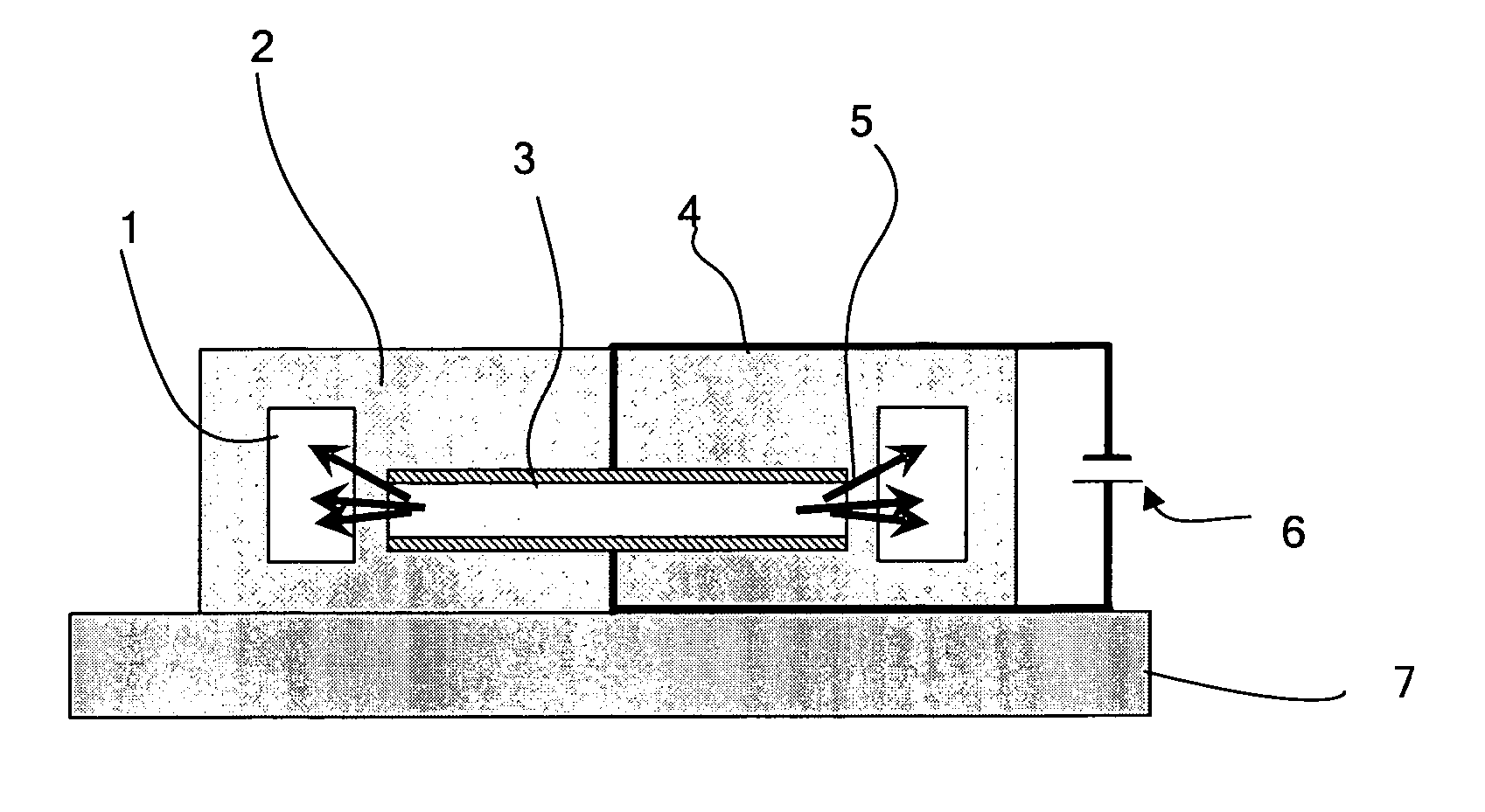
[0013] In a light emitting apparatus of the present invention, the EL emitting unit generates an electroluminescent (EL) light in the light emitting layer. That is, the EL emitting unit functions as an EL element. The EL light generated in the light emitting layer is blocked by the pair of light blocking layers disposed such that they sandwich the light emitting layer in between; therefore, the light emitting layer does not have to be thickened, and the EL light is radiated efficiently from the end (outer periphery) of the light emitting layer regardless of the thickness of the light emitting layer. On one hand, only about 20% of the EL light is radiated from the layer surface of the light emitting layer when the EL light generated in the light emitting layer is radiated from the layer surface. On the other hand, about 80% of the EL light is radiated from the end (outer periphery) of the light emitting layer when the EL light is radiated from the end (outer periphery) of the light emitting layer, and moreover, the 20% of the EL light radiated originally from the layer surface of the light emitting layer is radiated from the end (outer periphery) of the light emitting layer; as a result, about 100% of the EL light is radiated from the end (outer periphery) of the light emitting layer. The light emitting apparatus can utilize about 100% of the EL light and thus have high light utilization efficiency. Also, the EL light radiated from the end (outer periphery) of the light emitting layer is optically guided by the light emitting unit and emitted as it is or as a light modulated to have a wavelength different from that of the EL light. As a result, the light emitting apparatus can emit a light having the wavelength equal to or different from that of the EL light as a linear beam or a laser beam.
[0014] A light emitting apparatus of the present invention preferably has an aspect that the light emitting unit is equipped with an optical guiding member which optically guides the EL light radiated from the end of the light emitting layer. The optical guiding member equipped in the light emitting apparatus can suppress or reduce various losses, e.g. connection loss and
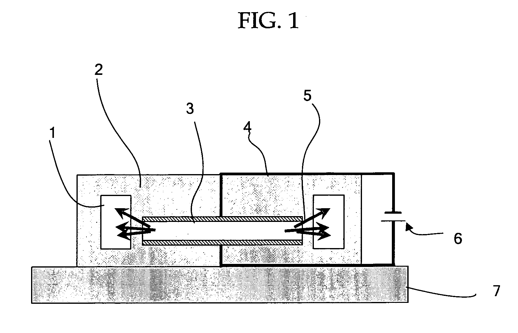
transmission loss, or attenuations. When the optical guiding member is designed in the form of a linear
waveguide, the excitation density of the light emitted from the light emitting unit may be adjusted to the desired value by adjusting the size (area) of the light emitting layer of the EL emitting unit (EL element), and thus it is possible to increase sufficiently the excitation density. In other words, the
luminous energy is proportional to the square of the
radius of the EL emitting unit while the density of the
driving current in the EL emitting unit is constant and directly proportional to the size (area) of the light emitting layer of the EL emitting unit. On the other hand, since the length of the linear
waveguide located opposite to the EL emitting unit, i.e. located surrounding the EL emitting unit, is directly proportional to the
radius of the EL emitting unit. Therefore, the increase in the size (area) of the light emitting layer in the EL emitting unit monotonously increases the excitation density in the linear waveguide. As a result, the adjustment of the size (area) of the light emitting layer in the EL emitting unit can turn the light emitted from the light emitting apparatus into a laser beam, i.e. provide a
laser oscillation.
[0015] In addition, a light emitting apparatus of the present invention preferably has an aspect that the light emitting unit is equipped with an optical guiding part which optically guides the EL light and a non-optical guiding part which does not optically guides the EL light and that the optical guiding part includes a light emitting material which absorbs the EL light radiated from the light emitting layer and emits a light. In the light emitting apparatus, the light emitting material of the optical guiding part absorbs the EL light and transits to an
excited state, and it emits a light when it returns to the
ground state (the EL light is modulated or amplified to a light having a different wavelength from that of the EL light). Therefore, an emission of a light having a different wavelength from that of the EL light to the exterior is induced, and the resulting light has superior intensity and
luminous energy. Here, the increase in the
electric current injected in the light emitting layer in the EL emitting unit (EL element) increase the
luminous intensity and the
luminous energy of the EL light generated in the light emitting layer, and this increase in the
luminous intensity and the luminous energy of the EL light increases the excitation density of the light emitting material as well. When the excitation density of the light emitting material exceeds its threshold, the
laser oscillation occurs, and a laser beam is emitted from the light emitting apparatus.
[0017] Furthermore, a light emitting apparatus of the present invention preferably has an aspect that the
refractive index of the non-optical guiding part is smaller than the
refractive index of the optical guiding part. In the light emitting apparatus, the
refractive index difference between the optical guiding part and the non-optical guiding part prevents the EL light, which is likely to leak out to the exterior from the periphery, from entering the non-optical guiding part; the EL light is reflected at the boundary between the optical guiding part and the non-optical guiding part, and it proceeds within the optical guiding part. Therefore, the optical guiding part serves as an optical waveguide, effectively suppressing the leak of the light proceeding in the optical guiding part to the exterior as well as reducing or suppressing the loss of the light guided into the optical guiding part, e.g.
transmission loss, or attenuations, and it can emit a light with large
luminous intensity.
[0018] Also, a light emitting apparatus of the present invention preferably has the optical guiding part arranged near the periphery of the light emitting layer. In the light emitting apparatus, the EL light emitted from the end (outer periphery) of the light emitting layer is efficiently guided into the optical guiding member without causing losses, e.g.
transmission loss, or attenuations.
[0019] Also, in a light emitting apparatus of the present invention, the optical guiding member preferably includes a light reflecting member near the periphery of the optical guiding part which reflects the EL light, emitted from the light emitting layer and transmitted in the optical guiding member, towards the optical guiding part. In the light emitting apparatus, a part of the EL light emitted from the end (outer periphery) of the light emitting layer is transmitted in the optical guiding part without being taken in the optical guiding part and reflected toward the optical guiding part. Therefore, the EL light emitted from the end (outer periphery) of the light emitting layer is efficiently guided by the optical guiding part without causing the losses, e.g. transmission loss, or attenuations.
