Light transmission/reception module and light transmission/reception device

a light transmission/reception module and light transmission technology, applied in the field of optical transceiver modules, can solve the problems of eminent degradation of communication characteristics, and achieve the effect of enhancing crosstalk and increasing path capacitan

Inactive Publication Date: 2007-04-19
PANASONIC CORP
View PDF4 Cites 14 Cited by
  • Summary
  • Abstract
  • Description
  • Claims
  • Application Information

AI Technical Summary

Benefits of technology

[0048] With this configuration, it is possible to avoid a case where a capacitance is generated between the conduction pattern on the bottom surface of the package and the first and second metal plates, which provides an effect like a capacitor, thereby increasing the capacitance of a path between the first and second metal plates and enhances the crosstalk.

Problems solved by technology

In particular, in case a signal is transmitted at a speed over gigabits / second, the resulting degradation of communications characteristic is eminent.

Method used


Image

  • Light transmission/reception module and light transmission/reception device
  • Light transmission/reception module and light transmission/reception device
  • Light transmission/reception module and light transmission/reception device

Examples


first embodiment

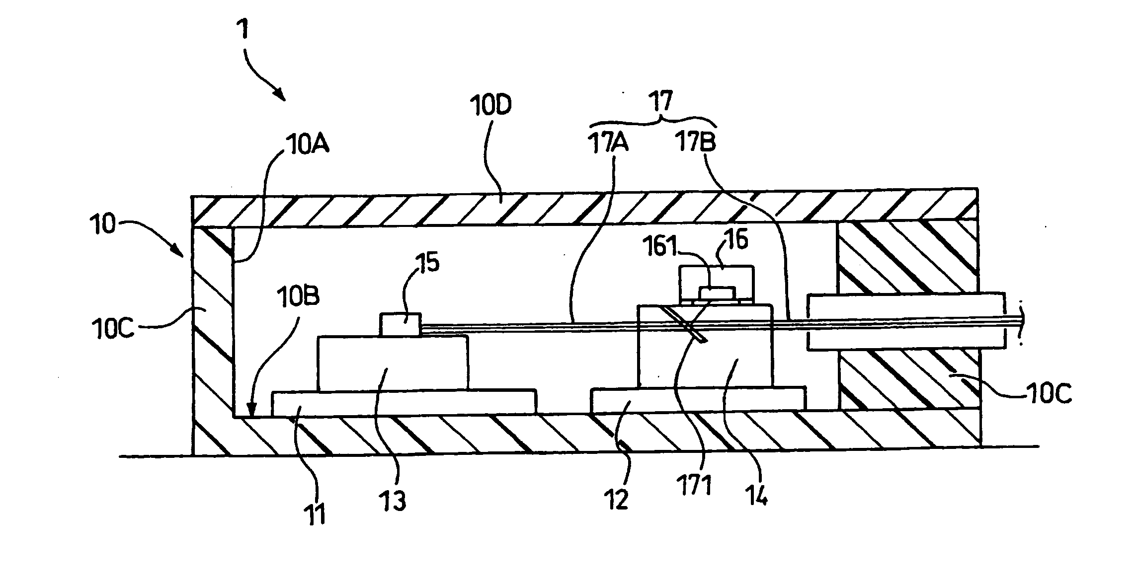
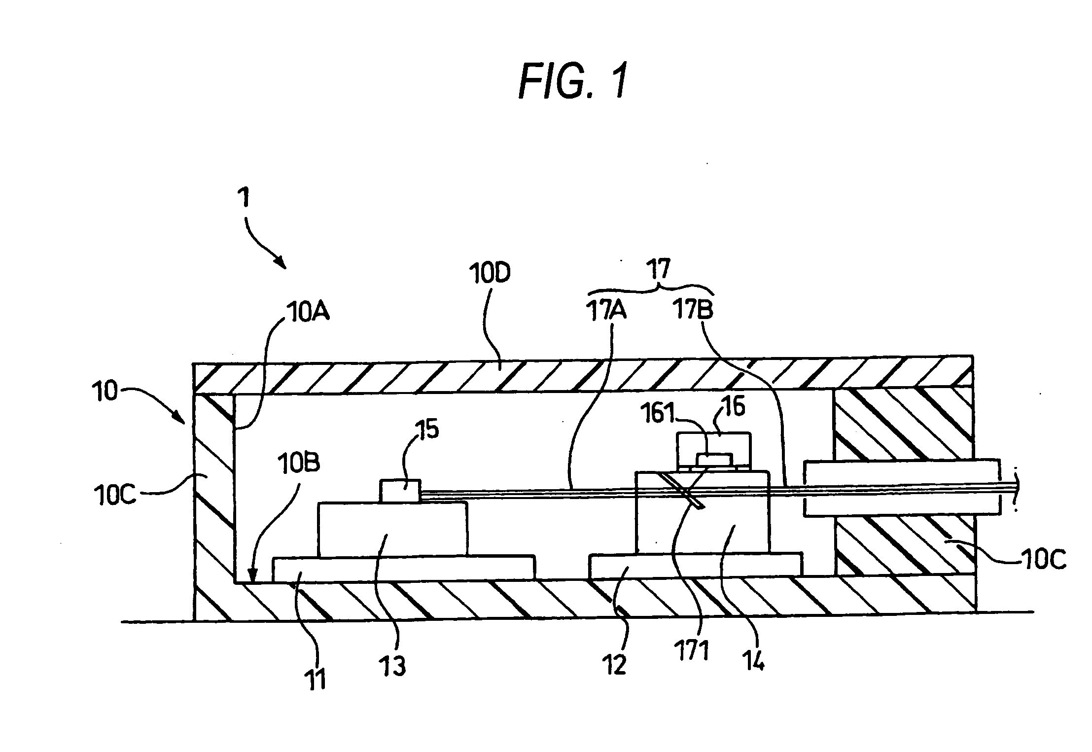
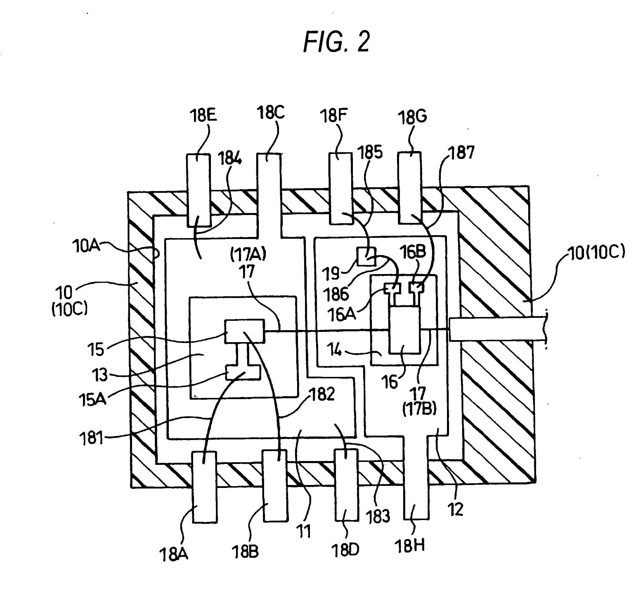
[0062]FIG. 1 and FIG. 2 show the configuration of an optical transceiver module according to the first embodiment of the invention. The optical transceiver module comprises, inside a package 10, a first metal plate 11 and a second metal plate 12 provided separately and independently of each other, a first substrate 13 and a second substrate 14 respectively provided on the metal plates, light emitting device 12 mounted on the first substrate 13, a photodetector 16 mounted on the second substrate 14, an optical waveguide 17, leads 18, and a capacitor 19.

[0063] The package 10 is a resin package formed of an appropriate resin material into a shape of an almost bottomed box in order to reduce the overall cost.

[0064] The package 10 comprises a removable lid 10D in order to enhance the strength and protect an optical device and an electric device inside, The lid 10D may be formed of the same resin material as the package main body or by an appropriate metal or ceramic in order to enhance...

second embodiment

[0109] Next, the second embodiment of the invention will be described referring to FIG. 6. The same portions in this embodiment as the first embodiment are given the same signs and the duplicate description is omitted.

[0110]FIG. 6 shows the configuration of an optical transceiver module 2 according to the second embodiment of the invention. The optical transceiver module 2 has the same configuration as the optical transceiver module 1 according to the first embodiment except that a preamplifier 21 and a second capacitor 22 are additionally mounted on the second metal plate 12.

[0111] The preamplifier 21 is used to enhance the amplification. Electrical connection is established between the terminal (not shown) of the preamplifier 21 used to connect to the cathode of the photodetector 16 and the cathode of the photodetector 16 via the sixth bonding wire 186 and the eighth bonding wire 231. Electrical connection is established between the terminal (not shown) of the preamplifier 21 us...

third embodiment

[0115] Next, the third embodiment of the invention will be described referring to FIG. 6. The same portions in this embodiment as the first embodiment are given the same signs and the duplicate description is omitted.

[0116]FIG. 7 shows the configuration of an optical transceiver module 3 according to the third embodiment of the invention. The optical transceiver module 3 of the third embodiment has the same configuration as the optical transceiver module 1 according to the first embodiment except that the former further comprises a through hole 10F that penetrates the bottom 10E of the package 10 at the bottom surface of the first metal plate 11, a conductive external connection metal 11A provided at the through hole 10F, a through hole 10G that penetrates the package 10 at the bottom surface of the second metal plate 12, and a conductive external connection metal 12A provided at the through hole 10G.

[0117] The first metal plate 11 and the conductive external connection metal 11A ...


PUM


Abstract

Providing an optical transceiver module that reduces electric crosstalk between a light emitting device and a photodetector while providing an excellent high-frequency characteristic, and an optical transceiver including the same. According to the invention, a first metal plate having a first substrate for mounting a light emitting device and a at second metal plate having a second substrate for mounting a photodetector are provided separately and independently of each other in a resin package, thus reducing the parasitic capacitance. This provides an optical transceiver module capable of suppressing electric crosstalk where part of a high-frequency signal causes a variation in the potential at a terminal of a photodetector while improving the high frequency characteristic in driving the light emitting device with a high-frequency signal, and an optical transceiver including the same.

Description

FIELD OF THE INVENTION [0001] The present invention relates to an optical transceiver module where a light emitting device and a photodetector are arranged in a same module in order to perform bidirectional communications and an optical transceiver including the same, and in particular to an optical transceiver module that reduces electrical interference between a light emitting device and a photodetector while providing an excellent high-frequency characteristic, and an optical transceiver including the same. BACKGROUND INFORMATION [0002] Recently, as the Internet communications are getting faster, an optical communications system called FTTH (Fiber To The Home) are in widespread use in trunk line communications systems as well as in subscriber line communications. In such an optical communications system, a method is employed where a single fiber cable is used to transmit optical signals having different wavelengths for upstream and downstream transmissions, for example using a ne...

Claims


Application Information

Patent Timeline
Patent Type & Authority Applications(United States)
IPC IPC(8): G02B6/36H01L31/02H01L31/0232H01L31/167H01L33/48H01L33/62H01S5/02H01S5/022
CPCH01L31/167H01S5/02216H01S5/02248H01S5/02284H01S5/06226H04B10/40H01L2224/45124H01L2224/45144H01L2924/00H01L2224/48091H01L2224/48145H01L2224/48247H01L2224/4911H01L2924/00014H01L2924/30107H01S5/02251H01S5/02325H01L2924/00012
Inventor NOJIMA, KAZUHIROFURUSAWA, SATOSHINISHIKAWA, TORUASANO, HIROAKI
Owner PANASONIC CORP
Why Eureka
Try Eureka