Capacitance multiplier circuit for PLL filter

Inactive Publication Date: 2007-04-26
ALICORP
View PDF5 Cites 8 Cited by
  • Summary
  • Abstract
  • Description
  • Claims
  • Application Information

AI Technical Summary

Benefits of technology

[0008] It is therefore a primary objective of the present invention to provide a capacitance multiplier circuit for a PLL filter in order to simplify the layout of capacitors for the purpose of reducing the layout space typical capacitors would occupy.

Problems solved by technology

The built-in PLLs inside a large digital system naturally creates the space use problem, especially when numerous PLLs are placed into a single chip.
However, the use of passive devices (especially the use of capacitors) takes a significant part of the chip layout.
Even some alternatives to the implement of capacitors have been proposed, they are not close to being ideal when it comes to unit-capacitance rate of these capacitors.
Simply because of the use of capacitors C100 and C101, as long as more and more second-order filters are going to be placed the entire space that PLLs would occupy increases accordingly, creating some disadvantages to layout of the corresponding integrated circuit design.

Method used


Image

  • Capacitance multiplier circuit for PLL filter
  • Capacitance multiplier circuit for PLL filter
  • Capacitance multiplier circuit for PLL filter

Examples


Embodiment Construction

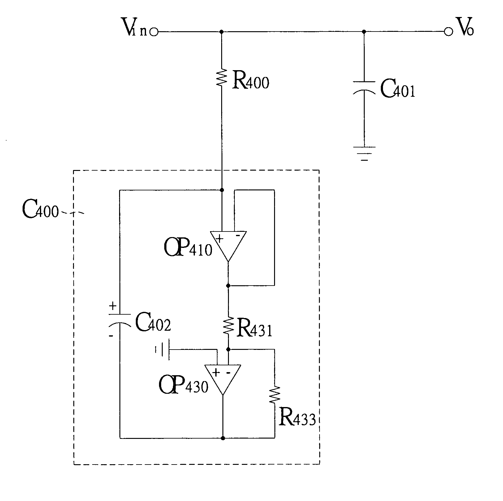
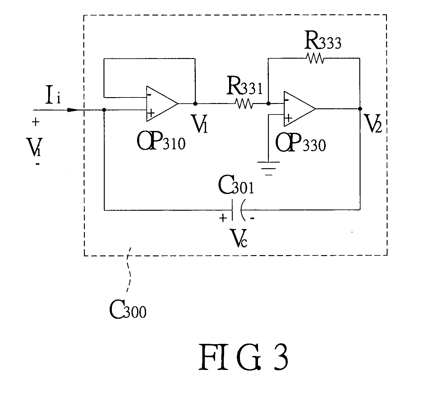
[0016] Please refer to FIG. 3 of a circuit diagram showing a capacitance multiplier circuit according to the present invention. The first operational amplifier OP310 includes one positive input end, one negative input end connected to the positive input end thereof that receives the input voltage Vi and input current Ii. The second operational amplifier OP330 includes one positive input end, one negative input end, and one output end connected to the negative input end thereof through a resistor R333 A capacitor C301 includes a positive end connected to the positive input end of the first operational amplifier OP310 and a negative end thereof connected to the output end of the second operational amplifier OP330. By doing so, the capacitance of the capacitor C301 could be increased by first and second operational amplifiers OP310 and OP330 at the rate configured by the ratio of resistors R331 and R333, so as to have an equivalent capacitance C300 for the entire capacitance multiplier...


PUM


Abstract

A capacitance multiplier circuit for a filter is provided. The capacitance multiplier circuit capable of adjusting its equivalent capacitance and used in the filter, applied to a Phase Locked Loops (PLLs) circuit, includes a first operational amplifier having a positive input end for receiving an input signal, an output end, and a negative input end connected to the output end, a second operational amplifier having a positive input end, a negative input end connected to the output end of the first operational amplifier through a first resistor, and an output end connected to the negative input end through a second resistor, and a capacitor connected between the positive input end of the first operational amplifier and the output end of the second operational amplifier. An equivalent capacitance of the capacitance multiplier circuit is adjusted by configuring the ratio of the first resistor and the second resistor.

Description

BAKCGROUND OF THE INVENTION [0001] 1. Field of the Invention [0002] The present invention relates to a capacitance multiplier circuit for a filter, and more particularly, to a capacitance multiplier circuit for substituting any given large capacitance capacitor in a Phase Locked Loops (PLLs) circuit. [0003] 2. Description of Prior Arts [0004] PLLs is widely used in numerous integrated circuit designs for the purpose, for example, of integrating timing signals, restoring the timing information from the data stream, or combining frequencies. The built-in PLLs inside a large digital system naturally creates the space use problem, especially when numerous PLLs are placed into a single chip. [0005] Prior arts generally employed passive devices such as resistors or capacitors to implement the filter-use PLLs. However, the use of passive devices (especially the use of capacitors) takes a significant part of the chip layout. Even some alternatives to the implement of capacitors have been pr...

Claims


Application Information

Patent Timeline
IPC IPC(8): G06G7/28
CPCH03H11/48H03L7/0891H03L7/093H03H11/483
Inventor CHEN, YU-CHENLU, YAO-CHUN
Owner ALICORP
Why Eureka
Try Eureka