Motor drive unit

a technology of motor drive and drive unit, which is applied in the direction of oscillation comparator circuit, electronic commutator, speed/torque control of dc motor, etc., can solve the problems of large circuit size and arithmetic circuit, and achieve the effect of simple configuration, reduced circuit area and small electronic devi

Inactive Publication Date: 2007-04-26
ROHM CO LTD
View PDF1 Cites 28 Cited by
  • Summary
  • Abstract
  • Description
  • Claims
  • Application Information

AI Technical Summary

Benefits of technology

[0025] The motor drive unit may be integrated on one semiconductor board. Moreover, “integrated” includes cases in which all constituent elements of the circuit are formed on a semiconductor board, and cases in which main constituent elements of the circuit are integrated, with some capacitors or resistors for adjusting a circuit constant arranged outside the semiconductor board. By integrating the motor drive unit as one LSI, the circuit area can be reduced.
[0026] Another embodiment of the present invention relates to an electronic device. The electronic device includes a single phase motor, and a motor drive unit for driving the single phase motor. According to this embodiment, since the energization time period for the coil can be controlled via a simple configuration, the electronic device can be made small.

Problems solved by technology

However, in cases in which the energization time period of the motor coil is arithmetically set, there is a problem in that an arithmetic circuit is necessary, and circuit size becomes large.

Method used


Image

  • Motor drive unit
  • Motor drive unit
  • Motor drive unit

Examples


first embodiment

[0042] An embodiment relates to an electronic device such as, for example, a mobile phone, or the like.

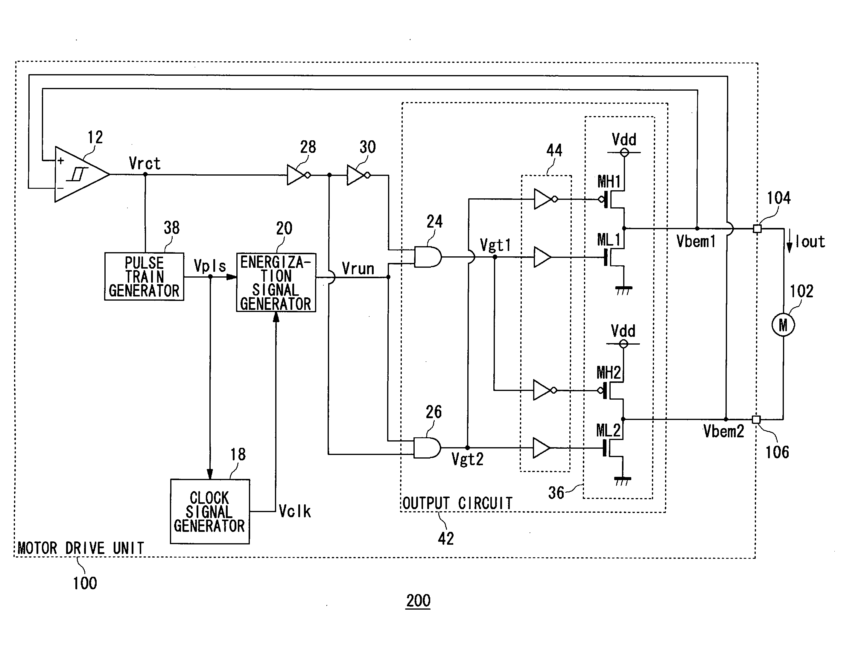
[0043]FIG. 1 shows a configuration of the electronic device 200 related to the first embodiment. The electronic device 200 is provided with a motor drive unit 100 and a motor 102.

[0044] The motor 102 is connected to a load such as, for example, a vibrator of the mobile telephone, or the like.

[0045] The motor drive unit 100 is provided with a first output terminal 104 and a second output terminal 106, forming a gateway for the drive current Iout for driving the motor 102.

[0046] The motor drive unit 100 supplies the drive current Iout to the motor 102, based on counter electromotive voltages Vbem1 and Vbem2 occurring at the first output terminal 104 and the second output terminal 106. The motor drive unit 100 is a function IC integrated on one semiconductor board.

[0047] The motor drive unit 100 is provided with a hysteresis comparator 12, a pulse train generator 38, a clock sign...

second embodiment

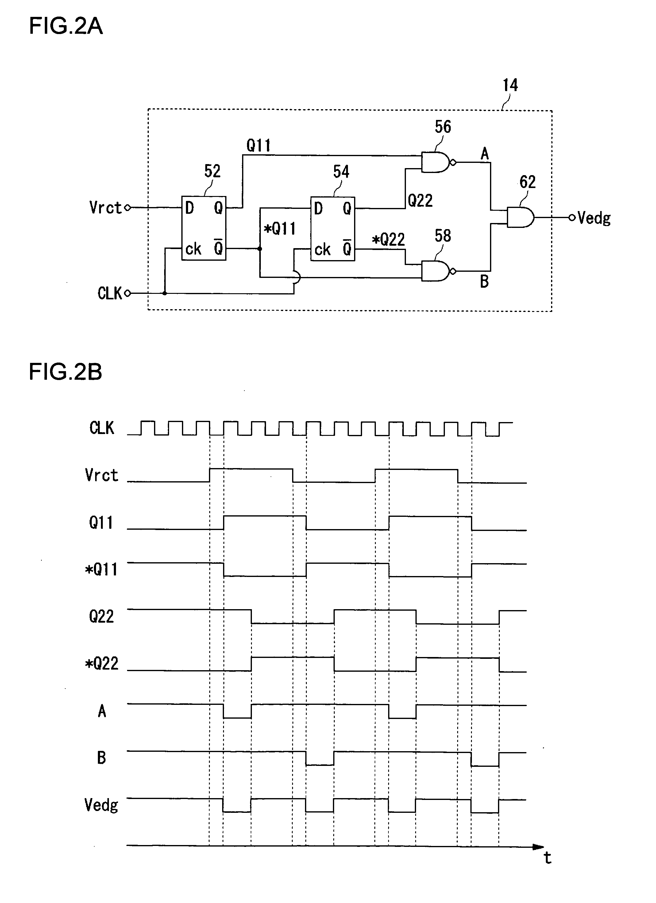
[0074] In the first embodiment, the pulse train generator 38 outputted, as it is, the edge detection signal Vedg, which is outputted from the edge detection circuit 14 included inside the pulse train generator 38, as the pulse train Vpls; in a second embodiment, however, an explanation is given concerning cases in which the pulse train generator 38 has a mask processing function for noise suppression. Furthermore, in cases of the second embodiment, N is a natural number, greater than or equal to 3.

[0075]FIG. 4 shows a configuration of an electronic device 200 related to the second embodiment. In FIG. 4, constituent elements that are identical with or equivalent to constituent elements of FIG. 1 are given the same reference symbols, and explanations thereof are omitted as appropriate.

[0076] The pulse train generator 38 includes an edge detection circuit 14 and a mask processor 40.

[0077] The edge detection circuit 14 creates a pulse every time an edge of a square wave signal Vrct i...

third embodiment

[0084] In a third embodiment, in order to realize noise suppression and silencing, an explanation is given for cases in which a function is added to make fluctuations in drive current Iout gradual, at starting and stopping of energization in the motor 102. Furthermore, in cases of the third embodiment, N is a natural number, greater than or equal to 2.

[0085]FIG. 6 shows a configuration of an electronic device 200 related to the third embodiment. In FIG. 6, constituent elements that are identical with or equivalent to constituent elements of FIG. 1 are given the same reference symbols, and explanations thereof are omitted as appropriate.

[0086] The electronic device 200 related to the third embodiment differs from that of the first embodiment principally in that a gradient signal generator 32 and a distributor 34 are additionally included.

[0087] The gradient signal generator 32 outputs a gradient signal Vslp whereby at an occasion when the energization signal Vrun rises, electrical...


PUM


Abstract

A motor drive unit (100) includes a pulse train generator 38, a clock signal generator (18), and an energization signal generator (20). The pulse train generator (38) creates a pulse each time an edge of a square wave signal (Vrct) is detected, and generates a pulse train (Vpls). The clock signal generator (18) generates a clock signal (Vclk) having a frequency N times a frequency of the pulse train (Vpls). The energization signal generator (20) generates an energization signal having a level that designates energization for a coil of a motor (102), for a time period in which the clock signal (Vclk) is counted M times, and, after that, having a level that indicates non-energization for the coil, for a time period in which the clock signal (Vclk) is counted (N−M) times.

Description

BACKGROUND OF THE INVENTION [0001] 1. Field of the Invention [0002] The present invention relates to drive technology for motors, and in particular, to a motor drive unit for driving a single phase motor and to electronic devices using the motor drive unit. [0003] 2. Description of the Related Art [0004] Generally, when a single phase brushless motor is driven, based on a position of a rotor detected by a sensor such as a Hall element or the like, timing of switching direction of a current supplying a motor coil (below, referred to as “current switching timing”) is detected. In order to realize smaller motors, a drive unit of a single phase brushless motor that detects the current switching timing without using a sensor such as a Hall element or the like, has been proposed (Patent Document 1). In cases of a single phase motor, by detecting a zero crossing in induced voltage generated in the motor coil, the current switching timing can be detected. [0005] Patent Document 1: Japanese ...

Claims


Application Information

Patent Timeline
Patent Type & Authority Applications(United States)
IPC IPC(8): H02P7/285H02P6/18H02P6/06H02P6/08H02P6/182H02P6/26
CPCH02P7/282H02P7/285
Inventor FUJII, NORIO
Owner ROHM CO LTD
Why Eureka
Try Eureka