Catalyst for synthesizing carbon nanocoils, synthesizing method of the same, synthesizing method of carbon nanocoils, and carbon nanocoils

a carbon nanocoil and catalyst technology, applied in the field of catalysts, can solve the problem of unclear micro-mechanics of this

Inactive Publication Date: 2007-05-03
JAPAN SCI & TECH CORP +3
View PDF13 Cites 16 Cited by
  • Summary
  • Abstract
  • Description
  • Claims
  • Application Information

AI Technical Summary

Benefits of technology

[0068] The forty-eighth mode of the present invention provides carbon nanocoils that are synthesized in accordance with any of the synthesizing methods for carbon nanocoils of the forty-first to forty-fourth modes. Accordingly, a large amount of carbon nanocoils can be synthesized, thus providing inexpensive nanocoils. In addition, carbon nanocoils having a uniform wire diameter and a uniform coil outer diameter can be provided when synthesized using a catalyst that is carried by a porous carrier. Accordingly, these carbon nanocoils having a uniform wire diameter and a uniform coil outer diameter can be utilized so that high quality nano-substances, such as nano-springs, nano-machines, electromagnet wave absorbers, electron emitters, nano-electron devices and hydrogen occluding bodies can be synthesized, so as to meet the requirements of various fields.

Problems solved by technology

However, the micro-mechanism for this is unclear at present.

Method used


Image

  • Catalyst for synthesizing carbon nanocoils, synthesizing method of the same, synthesizing method of carbon nanocoils, and carbon nanocoils
  • Catalyst for synthesizing carbon nanocoils, synthesizing method of the same, synthesizing method of carbon nanocoils, and carbon nanocoils
  • Catalyst for synthesizing carbon nanocoils, synthesizing method of the same, synthesizing method of carbon nanocoils, and carbon nanocoils

Examples


example 1

Synthesis of Carbon Nanocoils from Fe•In•Sn Oxide Thin Film

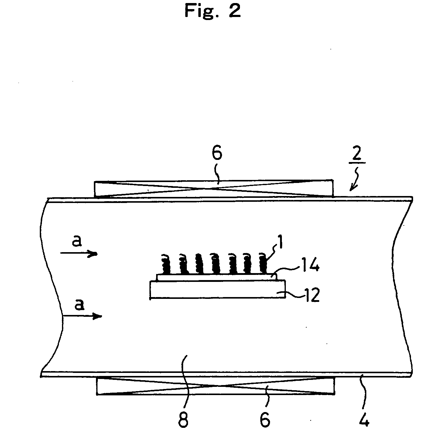
[0178] An Fe•In•Sn oxide thin film having a film thickness of 200 nm was formed on the (001) surface of an Si substrate. Carbon nanocoils were synthesized at approximately 700° C. with this oxide thin film as a starting catalyst by means of the carbon nanocoil synthesizing apparatus shown in FIG. 2. 60 sccm of a C2H2 gas was utilized as a carbon compound gas, which is a material gas, and 200 sccm of a He gas was used as a carrier gas.

[0179] The substrate was taken out 1 second, 5 seconds, 10 seconds, 1 minute, 5 minutes and 30 minutes after the gases were made to flow, and the state on the surface of the substrate was observed through a scanning electron microscope (SEM). The change in the Fe•In•Sn oxide thin film and the degree of growth of carbon nanocoils was confirmed from the respective states on the surface of the substrate.

[0180]FIG. 11 is a SEM image of the Fe•In•Sn oxide thin film, taken at a magnification of 50,...

example 2

Formation of Carbide Catalyst Fine Particles from 1 sccm of C2H2

[0185] In Example 1, the C2H2 gas, which is a material gas, was supplied at 60 sccm, and therefore, the growth rate of the carbide catalyst fine particles was too great. Therefore, it was examined how the first intensity peak of the diffraction intensity of Fe3InC0.5 increases as time elapses when the C2H2 gas was supplied at 1 sccm.

[0186] The C2H2 gas was set at 1 sccm, He was set at 50 sccm, and the heating temperature was set at 700° C. A substrate on which an Fe•In•Sn oxide thin film that is exactly the same as that of FIG. 12 was placed in the reaction chamber. This substrate kept being irradiated with X-rays, and a diffraction intensity of 2θ=39.62° (in the vicinity of approximately 40°) was measured where the first peak was obtained, as time elapsed.

[0187]FIG. 13 is a graph showing the first intensity peak of the diffraction intensity where 2θ is 39.62° (in the vicinity of approximately 40°) as time elapsed. T...

example 3

Control of Diameter of Catalyst Fine Particles of Fe3InC0.5

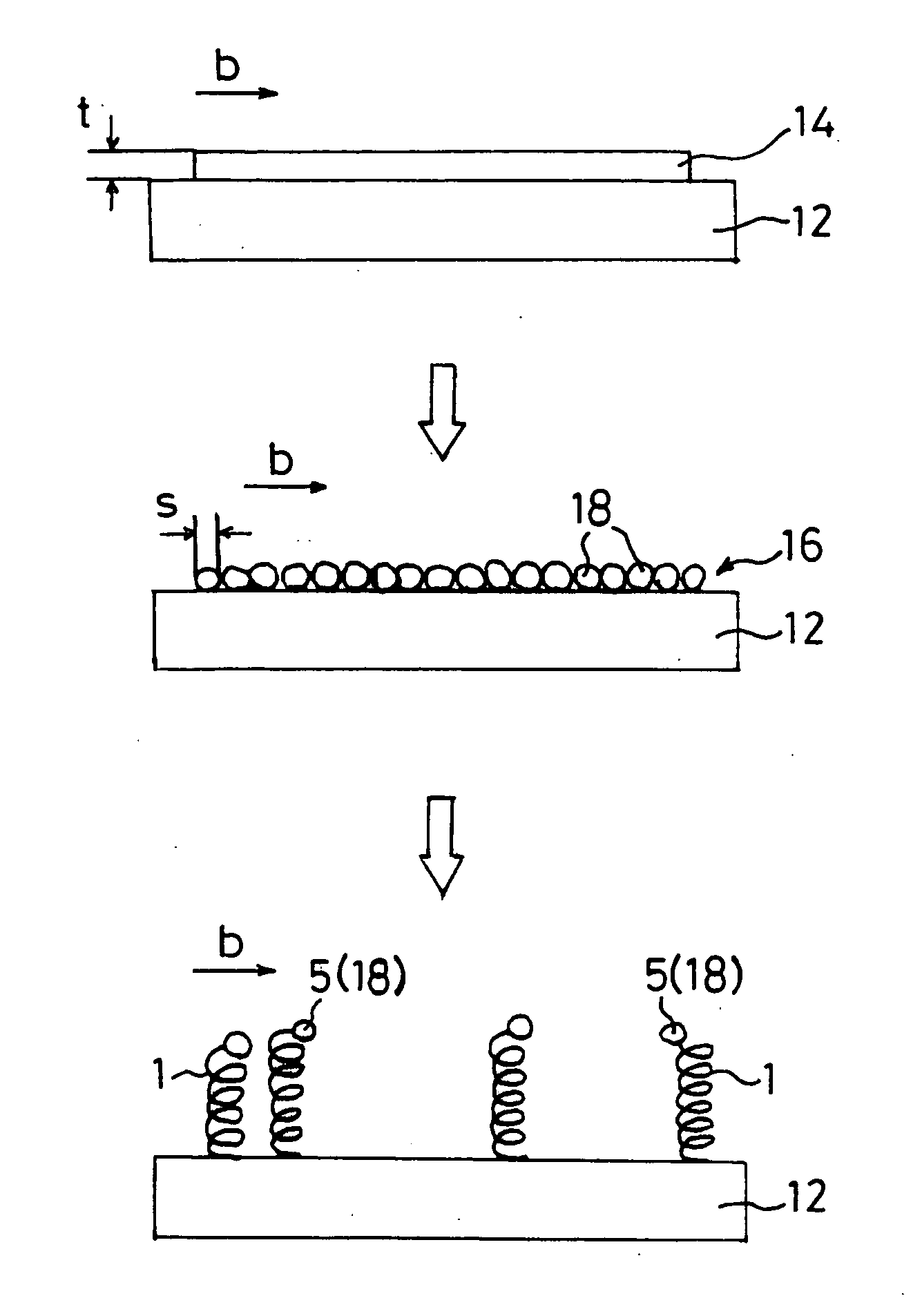
[0189] Growth conditions may be changed in order to control the particle diameter (diameter s) of the catalyst fine particles of Fe3InC0.5. In this Example 3, the growing temperature, that is, the heating temperature of the substrate (temperature of the reaction chamber), was changed between 650° C. and 700° C. when the carbide catalyst fine particles were formed, and carbon nanocoils were grown using these carbide catalyst fine particles.

[0190] The C2H2 gas was set at 1 sccm, He was set at 50 sccm, and the heating temperature was set at 650° C. and 700° C. In exactly the same manner as in FIG. 12, a substrate was placed in a reaction chamber with an Fe•In•Sn oxide thin film as a starting catalyst. Catalyst fine particles of Fe3InC0.5 were grown on this substrate, and carbon nanocoils were grown using this substrate.

[0191]FIG. 14 is a scanning electron microscope image of the carbide catalyst fine particles and grown carb...


PUM

PropertyMeasurementUnit
outer diameteraaaaaaaaaa
diameteraaaaaaaaaa
diffraction angleaaaaaaaaaa

Abstract

A method for synthesizing carbon nanocoils with high efficiency, by determining the structure of carbon nuclei that have been attached to the ends of carbon nanocoils and thus specifying a true catalyst for synthesizing carbon nanocoils is implemented. The catalyst for synthesizing carbon nanocoils according to the present invention is a carbide catalyst that contains at least elements (a transition metal element, In, C) or (a transition metal element, Sn, C), and in particular, it is preferable for the transition metal element to be Fe, Co or Ni. In addition to this carbide catalyst, a metal catalyst of (Fe, Al, Sn) and (Fe, Cr, Sn) are effective. From among these, catalysts such as Fe3InC0.5, Fe3InC0.5Snw and Fe3SnC are particularly preferable. The wire diameter and the coil diameter can be controlled by using a catalyst where any of these catalysts is carried by a porous carrier.

Description

TECHNICAL FIELD [0001] The present invention relates to a catalyst for synthesizing carbon nanocoils in accordance with a chemical vapor deposition method, in particular, a catalyst for synthesizing carbon nanocoils with which carbon nanocoils can be efficiently synthesized, a synthesizing method of the same, a synthesizing method of carbon nanocoils, and carbon nanocoils that are ultimately obtained. BACKGROUND ART [0002] Carbon nanocoils that are wound in coil form of which the outer diameter is no greater than 1000 nm have been synthesized. Carbon nanocoils have similar properties as carbon nanotubes and significant electromagnetic induction, and thus, are useful for the material for the head of a hard disc and for an absorber of electromagnetic waves. In addition, carbon nanocoils have spring elasticity that makes it return to its original length when expanded to a length that is twice as long, and therefore, have been attracting attention as a material for the springs of micro-...

Claims


Application Information

Patent Timeline
Patent Type & Authority Applications(United States)
IPC IPC(8): D01F9/12B01J23/835B01J27/22B01J29/14C01B31/02C01B31/30D01F9/127
CPCB01J23/835B01J27/22B01J29/146B82Y30/00B82Y40/00C01B31/0293C01B31/30C01P2002/72C01P2004/03C01P2004/13C01P2006/16D01F9/127C01B32/18C01B32/90B01J23/825
Inventor NAKAYAMA, YOSHIKAZUPAN, LUJUNNOSAKA, TOSHIKAZUSUEKANE, OSAMUOKAZAKI, NOBUHARUNAGASAKA, TAKESHIGOTO, TOSHIKITSUCHIYA, HIROYUKIOKAWA, TAKASHISHIONO, KEISUKE
Owner JAPAN SCI & TECH CORP
Why Eureka
Try Eureka