Device and method for the reduction of particles in the thermal treatment of rotating substrates

a technology of rotating substrates and devices, applied in the field of semiconductor wafers, can solve the problems of special constraints on the flow of gas, rotation produces mechanical abrasion, and therefore particles, and the occurrence of particles caused by mechanical abrasion cannot be avoided altogether, so as to achieve simple and cost-effective effects

Inactive Publication Date: 2007-05-03
ASCHNER HELMUT +5
View PDF16 Cites 18 Cited by
  • Summary
  • Abstract
  • Description
  • Claims
  • Application Information

AI Technical Summary

Benefits of technology

[0013] Therefore, an object of this invention is to, in a simple and cost-effectiv

Problems solved by technology

The process should, for example, be realized such that particles which are located in the process chamber can not reach the substrate to be treated thermally, and this places special constraints upon the flow of gas.
However, rotation produces mechanical abrasion, and therefore particles.
Despite this, the occurrence of particles caused by mechanical abrasion can not be avoided altogether.
Despite this, particles resulting from mechanical abrasion can not be totally prevented from passing into the process atmosphere.
A further disadvantage of gas-driven arrangements is that rotation gas and process gas may mix together, and so have an unfavorable effect upon the process realization.
The use of different gases and gas mixtures for the thermal process realization and for the rotation drive is often only possible to a limited degree when using a gas-drive

Method used


Image

  • Device and method for the reduction of particles in the thermal treatment of rotating substrates
  • Device and method for the reduction of particles in the thermal treatment of rotating substrates
  • Device and method for the reduction of particles in the thermal treatment of rotating substrates

Examples


Embodiment Construction

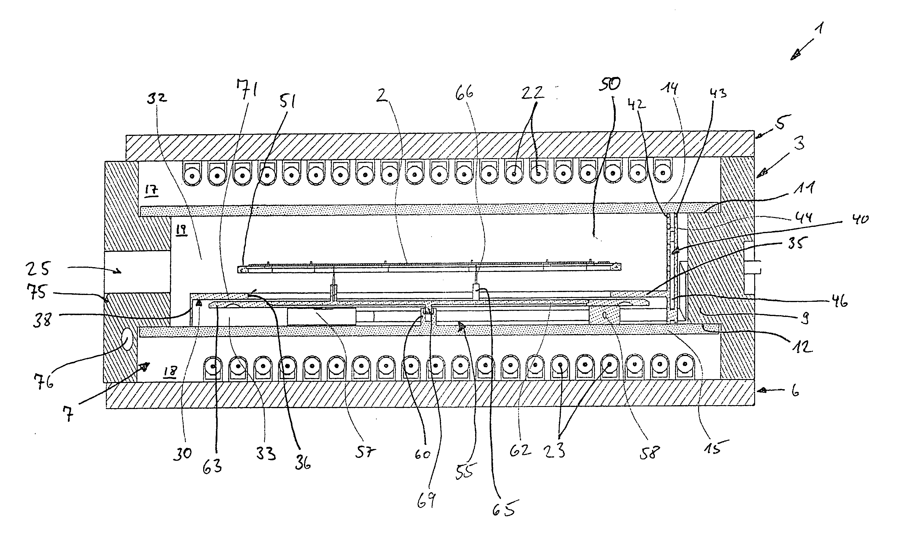
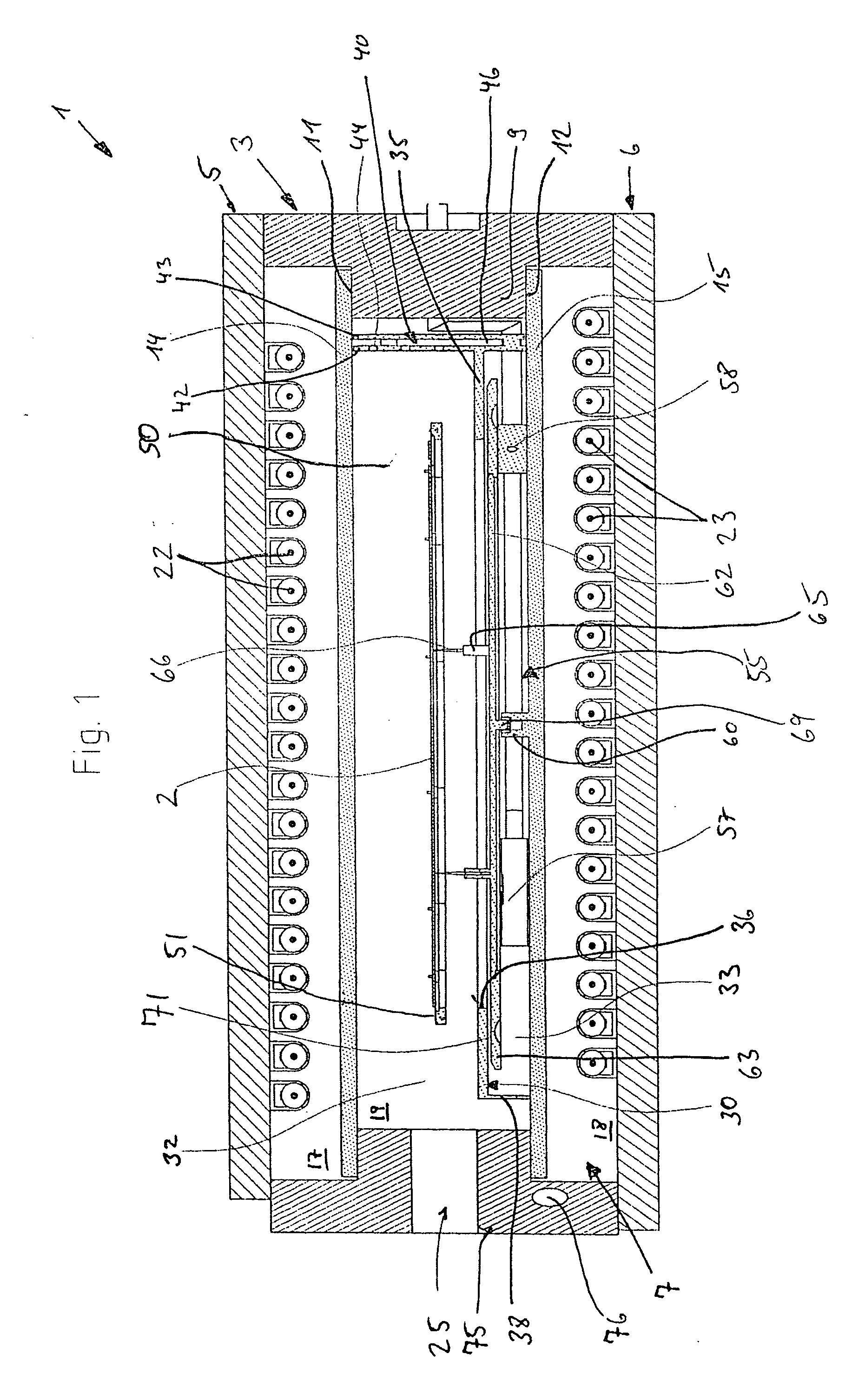
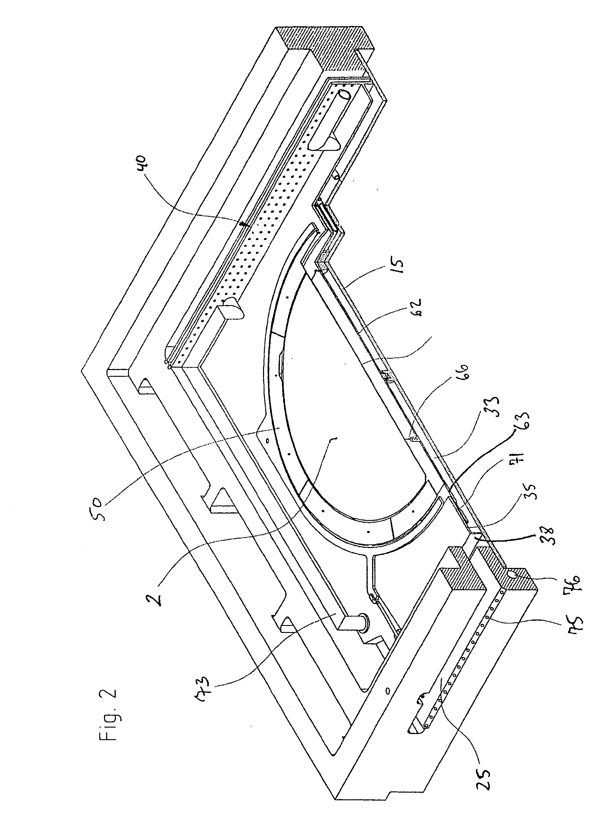
[0037]FIG. 1 schematically shows, in a cross-section, a preferred example of an embodiment of a rapid heating system 1, whereas FIG. 2 shows a partially sectioned perspective illustration of the rapid heating system 1. The rapid heating system 1 is provided for the thermal treatment of a disc-shaped substrate such as a semiconductor wafer.

[0038] In all of the figures, the same or similar components are identified with the same reference numbers. The relative terms used in the following description such as for example upper, lower etc. relate purely as examples to the representation in the figures and should not restrict the invention in any way.

[0039] The rapid heating system 1 has a frame-like main body 3, the upper and lower ends of which are covered by plate elements 5, 6 so as to form a rapid heating chamber 7.

[0040] The frame-like main body has an inwardly extending projection 9 which forms upper and lower circumferential contact surfaces 11 and 12. Upper and lower plate ele...


PUM

PropertyMeasurementUnit
Fractionaaaaaaaaaa
Pressureaaaaaaaaaa
Lengthaaaaaaaaaa

Abstract

A device and a method for reducing particle exposure to substrates during thermal treatment are disclosed. Semiconductor wafers may be rotated on a device within a process chamber divided into two partial chambers such that a first partial chamber contains the substrate to be thermally treated and a second partial chamber contains at least parts of the rotation device. Between the partial chambers, a flow of gas is set such that gas from the second partial chamber is substantially prevented from passing into the first partial chamber. In this way, particles which are produced by rotation abrasion in the second partial chamber are largely prevented from passing onto the substrate to be thermally treated. This device and this method are particularly advantageous if the rotation is realized by means of a gas drive, wherein the gas used for the rotation can be introduced directly into the second partial chamber.

Description

RELATED APPLICATIONS [0001] The present application is based on and claims priority to U.S. Provisional Application No. 60 / 696,876, filed Jul. 6, 2005, and German Patent Application No. 10 2005 024 118.2, filed May 25, 2005.FIELD OF THE INVENTION [0002] This invention relates to a device and a method for the thermal treatment of substrates, in particular semi-conductor wafers, in a process chamber, the substrate to be treated being rotated during thermal treatment within the process chamber. BACKGROUND OF THE INVENTION [0003] Rapid heating units, so-called RTP systems for the thermal treatment of substrates, such as e.g. semi-conductor wafers, are well known in the production of semiconductors. Units of this type are described, for example, in U.S. Pat. No. 5,359,693 and U.S. Pat. No. 5,580,830. They are used for the thermal treatment of substrates, preferably wafers, which are preferably made of silicon, but also of other semi-conductor materials such as germanium, SiC or other con...

Claims


Application Information

Patent Timeline
IPC IPC(8): B05D3/02H01L21/00
CPCF27B5/04F27B17/0025F27D5/0037H01L21/324H01L21/67115H01L21/6719H01L21/68792
Inventor ASCHNER, HELMUTSCHMID, PATRICKTHEILER, THOMASHEUDORFER, OTTMARWEBER, KARSTENO'CARROLL, CONOR
Owner ASCHNER HELMUT
Why Eureka
Try Eureka