
Method for producing functionally graded coatings using cold gas-dynamic spraying

a technology of functional graded coating and cold gas spraying, which is applied in the direction of molten spray coating, coating, plasma technique, etc., can solve the problems of high stress load and high heat, unacceptably high degradation rate, and limited use of components

Inactive Publication Date: 2007-05-03
HONEYWELL INT INC
View PDF15 Cites 21 Cited by
  • Summary
  • Abstract
  • Description
  • Claims
  • Application Information

AI Technical Summary

Benefits of technology

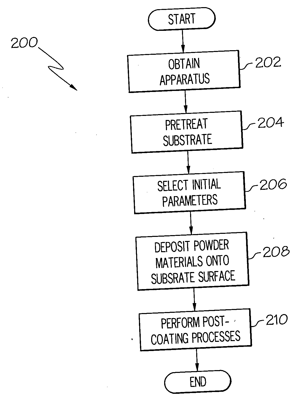
[0007] In another exemplary embodiment, the method comprises cold gas-dynamic spraying a first powder mixture on the substrate surface, the first powder mixture formulated to form a first portion of the graded coating and comprising a first component and a second component. Additionally, the method includes gradually decreasing the first component and increasing the second component to form additional powder mixtures, while cold gas-dynamic spraying the additional powder mixtures over the portion of the graded coating to form a second portion of the graded coating.
[0008] In still another exemplary embodiment, the method comprises the step of cold gas-dynamic spraying a

Problems solved by technology

Thus, during operation of the turbine engine, these components are subjected to stress loadings and high heat (often in excess of 2000° F.).
The high stress and heat can cause erosion, oxidation, corrosion, thermal fatigue cracks and / or foreign object damage in the component, resulting in unacceptably high rates of degradation.
Conventionally, graded coatings have been deposited onto the component using one of various thermal spraying techniques, for example, low pressure plasma spraying, high velocity oxygen fuel thermal spraying, arc-plasma spraying, and electric wire arc spraying; however, these techniques suffer from certain drawbacks, which have made them expensive and limited their use.
For example, because the coating material and component are both heated during the deposition process, the component may be more prone to distortion.
As a result, the coating may be deposited layer by layer and physical differences between each of the layers may promote cracking.
Also, spraying mixtures of powders to obtain a gradual transition from one layer to the next is relatively difficult to achieve due to the different temperatures (spray conditions) required for depositing each powder.
Moreover, thermal spraying is generally costly and time-consuming to implement, especially when depositing more than one layer.

Method used


Image

  • Method for producing functionally graded coatings using cold gas-dynamic spraying
  • Method for producing functionally graded coatings using cold gas-dynamic spraying
  • Method for producing functionally graded coatings using cold gas-dynamic spraying

Examples


Embodiment Construction

[0013] The following detailed description of the invention is merely exemplary in nature and is not intended to limit the invention or the application and uses of the invention. Furthermore, there is no intention to be bound by any theory presented in the preceding background of the invention or the following detailed description of the invention.

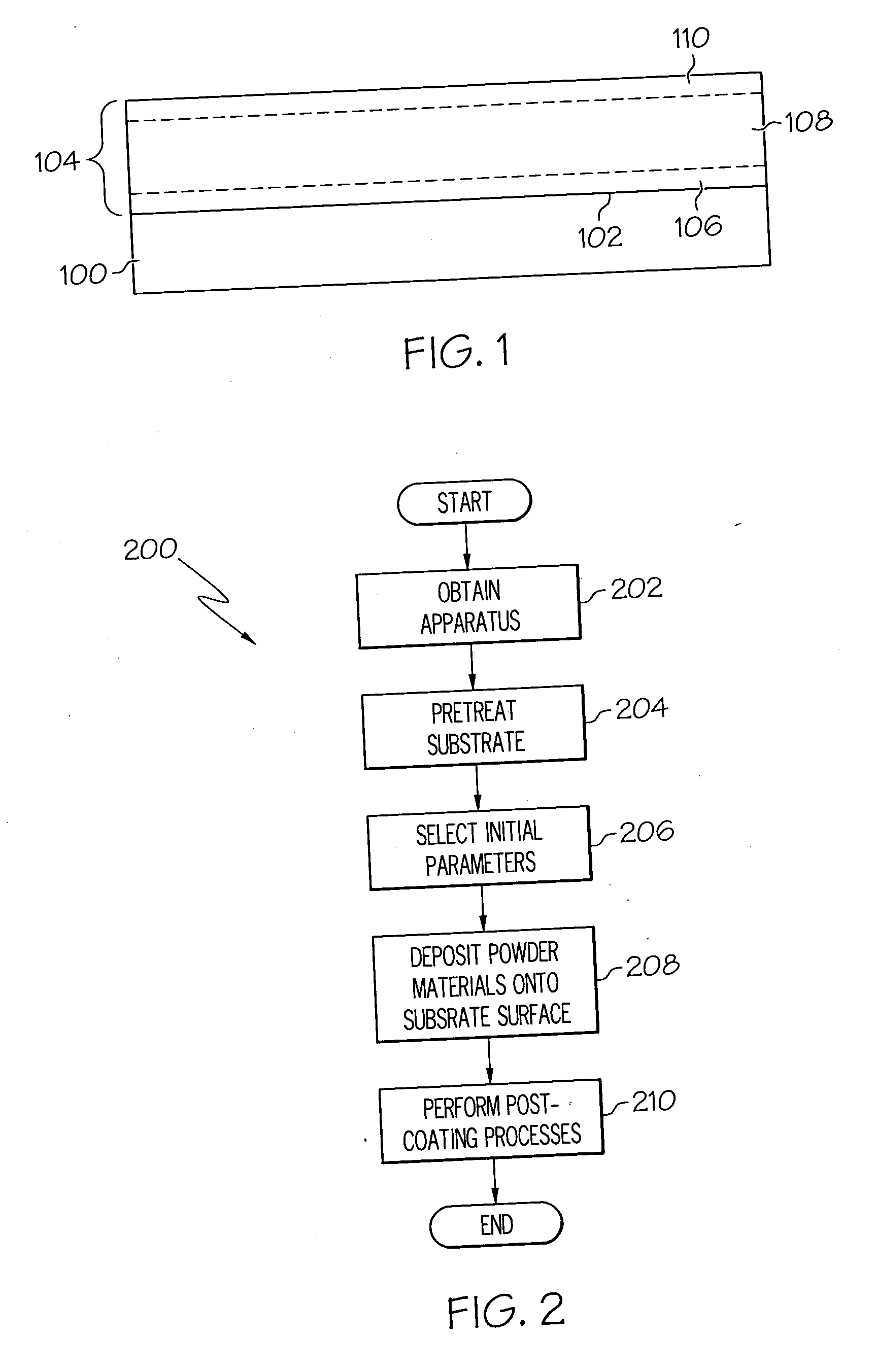
[0014] Turning now to FIG. 1, an exemplary substrate 100 having a graded coating 104 formed over its surface 102 is shown. The substrate 100 may be any one of numerous components, such as a turbine blade or disk, that may need a graded coating formed thereon. The graded coating 104 preferably includes a first section 106 having a first composition, a second section 108 wherein the first composition gradually changes into a second composition, and a third section 110 having the second composition. It will be appreciated that although each of the sections are delineated by dotted lines, the sections preferably blend into each other and the b...


PUM

PropertyMeasurementUnit
Pressureaaaaaaaaaa
Compositionaaaaaaaaaa
Densityaaaaaaaaaa

Abstract

A method is provided for forming a graded coating on a surface of a substrate. The method comprises the step of cold gas-dynamic spraying powder mixtures on the substrate surface to form the graded coating thereon. The method does not distort the substrate and does not require the use of an apparatus that needs to be stopped and re-started each time the composition of the graded coating changes. Moreover, the method is generally inexpensive, efficient, and yields high quality graded coatings.

Description

TECHNICAL FIELD [0001] The present invention relates to coating substrates, such as gas turbine engine components, with a coating having high strength and hardness and, more particularly, to methods of forming a graded coating on the substrate. BACKGROUND [0002] Turbine engines are used as the primary power source for aircraft, in the forms of jet engines and turboprop engines, as auxiliary power sources for driving air compressors, hydraulic pumps, on aircraft, and as stationary power supplies, such as backup electrical generators for hospitals and the like. The same basic power generation principles apply for all these types of turbine engines. Compressed air is mixed with fuel and burned, and the expanding hot combustion gases are directed against stationary turbine vanes in the engine. The vanes turn the high velocity gas flow partially sideways to impinge on the turbine blades mounted on a rotationally mounted turbine disk or wheel. [0003] The force of the impinging gas causes ...

Claims


Application Information

Patent Timeline
IPC IPC(8): B05D1/08H05H1/26
CPCC23C24/04
Inventor RAYBOULD, DEREKDUFFY, TIMOTHY R.FLOYD, MARGARET M.
Owner HONEYWELL INT INC
Learn More