

Variable resonator
- Summary
- Abstract
- Description
- Claims
- Application Information
AI Technical Summary
Benefits of technology
Problems solved by technology
Method used
Image

Examples
first embodiment
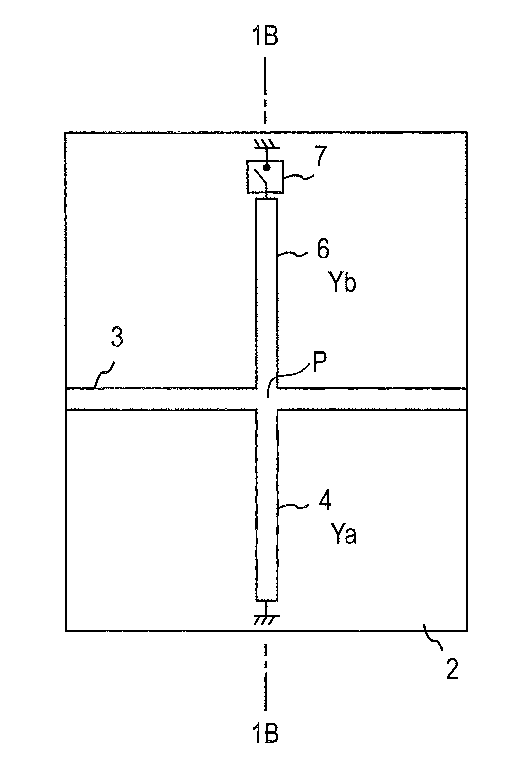
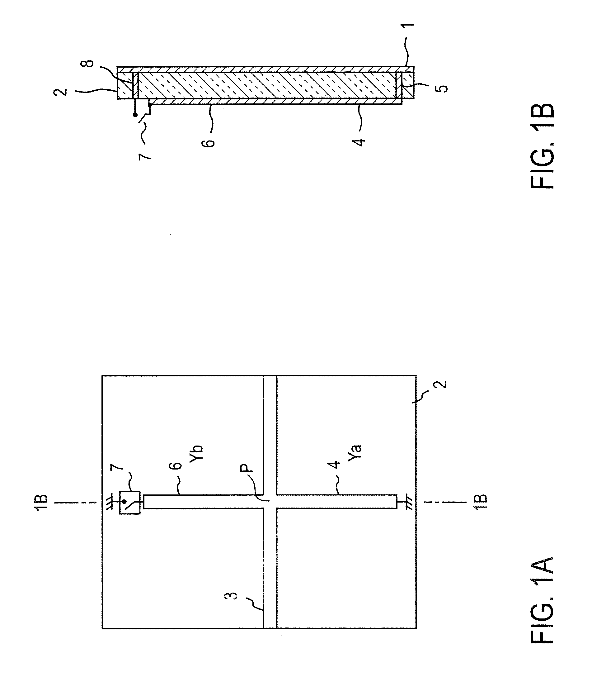
[0073]FIG. 1 shows a resonator having a microstrip line structure according to the present invention. FIG. 1A is a plan view, and FIG. 1B is a cross-sectional view taken along the line 1B-1B in FIG. 1A. An input / output line 3 is formed on the front surface of a dielectric substrate 2, and the back surface of the dielectric substrate 2 is grounded via a ground conductor 1. A high-frequency signal is input to one end of the input / output line 3. In this example, a first resonator 4 is connected to the input / output line 3 at one end thereof, extends in a direction perpendicular to the input / output line 3 and is grounded to the ground conductor 1 at the other end via a conductor passing through an interlayer connection (referred to as via hole hereinafter) 5. The characteristic impedance of the first resonator 4 is Z0.
[0074] One end of a second resonator 6 is connected to the input / output line 3 at the point of connection of the one end of the first resonator 4 to the input / output line ...
second embodiment
[0118] According to the first embodiment described above, a variable resonator having a wide range of variation of frequency can be provided. However, the interval between the resonance frequencies is relatively wide, such as integral multiples of the fundamental frequency. As a second embodiment, there will be described examples of a variable resonator that has a resonance frequency capable of being more finely resolved (that is, changed in smaller steps) and has a wider range of variation of frequency.
[0119] In advance of the description of the second embodiment, the skin effect, which is utilized also in the prior art shown in FIG. 22, will be described.
[0120] Electric signals transmitted through a resonance line are more likely to be concentrated at the outer periphery of the resonance line as the frequency increases. This is due to the skin effect of high-frequency signals. In the case where an electric signal is transmitted through a conductor, the penetration depth of the s...
example 1
[0123]FIGS. 9A and 9B show an example in which the skin effect is applied to the variable resonator according to the present invention, thereby increasing the resolution of the variable resonance frequency.
[0124] A dielectric substrate 90 has a rectangular strip shape in a plan view, and an input / output line 3 formed on the dielectric substrate 90 and extends in parallel with the shorter sides thereof at about the middle of the longer sides thereof. On one side of the input / output line 3, a first resonator 4 is connected perpendicularly to the input / output line 3 at about the middle of the input / output line 3. A second resonator 6 is similarly connected on the other side of the input / output line 3.
[0125] In this example 1, the first resonator 4 and the second resonator 6 have shapes that exhibit the skin effect and have an increased resolution of the resonance frequency. The resonance line of the first resonator 4 comprises a combination of two kinds of lines including a first lin...
PUM
 Abstract
Description
Claims
Application Information