
Lateral flow assay device with multiple equidistant capture zones

a technology of lateral flow and capture zone, which is applied in the field of assay devices with multiple capture zones, can solve the problems of increasing the complexity of assay, sample and lateral flow capture zone, sample concentration differences, and sample concentration differences

Inactive Publication Date: 2007-05-10
ORASURE TECHNOLOGIES
View PDF10 Cites 12 Cited by
  • Summary
  • Abstract
  • Description
  • Claims
  • Application Information

AI Technical Summary

Benefits of technology

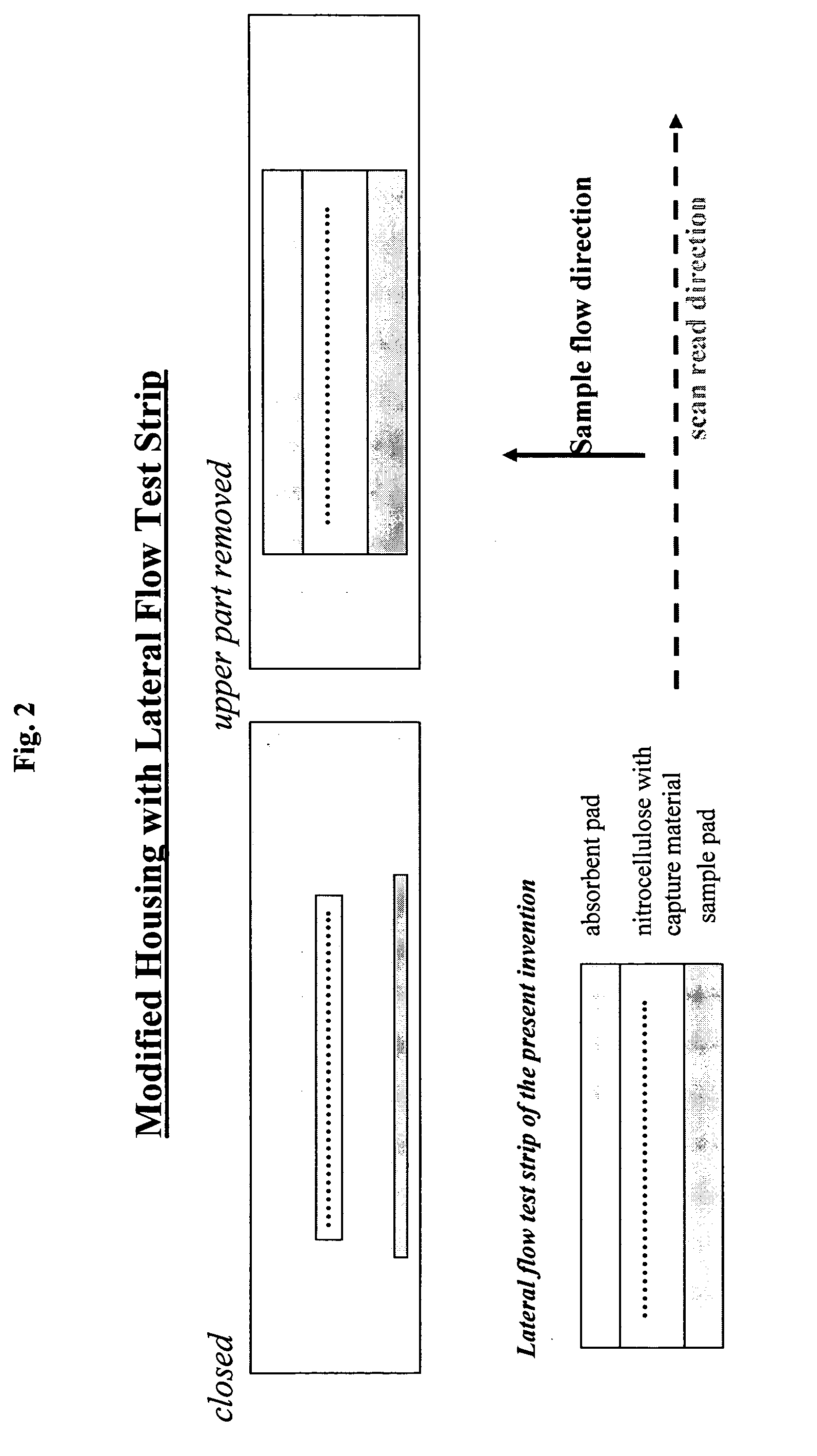
[0014] The invention addresses the problem of sample exhaustion by non-specific analyte capture occurring in existing assay devices and permits the simultaneous testing of numerous different analytes present in one sample. Specifically, two or more zones of analyte capturing compositions, or target capture molecules, are immobilized on the test strip substantially equidistant from the sample receiving area and in a linear array which is perpendicular to the sample flow rather than parallel to the flow of the sample. The placement of capture or test zones substantially equidistant from the sample receiving area and in a linear array perpendicular to the sample flow direction eliminates

Problems solved by technology

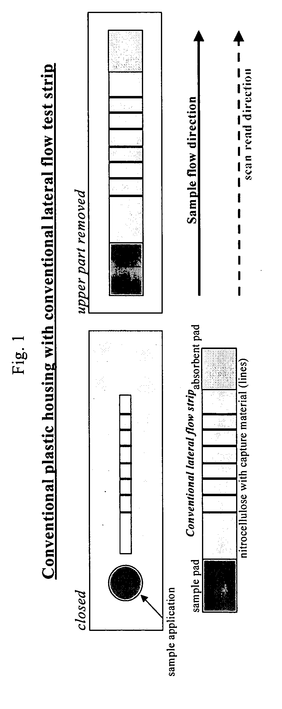
There is a limit to the number of target capture lines that can be used with the conventional lateral flow assay format.
The limit arises, in part, because succeeding capture lines, located further away from the sample pad, suffer from the non-specific capture of sample and analyte by the preceding capture zones and the materials used to construct the assay device.
This non-specific capture, which also occurs in the assay strip material itself, results in the sample supply becoming exhausted prior to contacting all target capture lines.
Clearly, the possible detection of both proteins and nucleic acids from one sample on one lateral flow test strip is likely to further increase complexity of the assay, the sample and the lateral flow capture zones.

Method used


Image

  • Lateral flow assay device with multiple equidistant capture zones
  • Lateral flow assay device with multiple equidistant capture zones
  • Lateral flow assay device with multiple equidistant capture zones

Examples


example 1

DIG-Biotin DNA Dilution Series

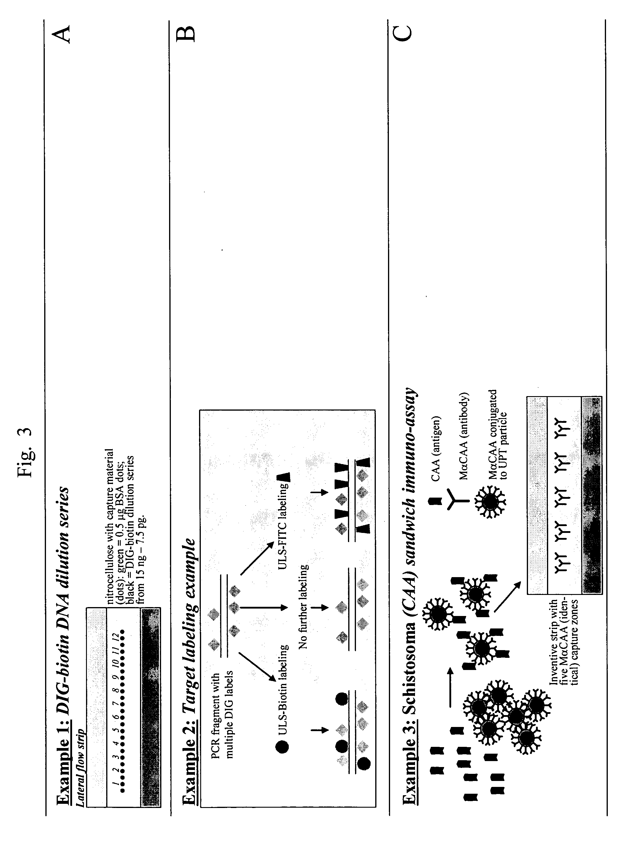
[0038] A dilution series of DIG-biotin haptenized DNA was mixed with Avidin-D and spotted on the nitrocellulose membrane of conventional strips and inventive strips. The double-stranded DIG-biotin DNA, containing one DIG and one biotin on opposite sites, has a size of 452 bp (base pairs). A dilution series of 12 steps ranking from 15 ng to 7.5 pg (consecutive 2× dilution steps) was mixed with a fixed amount (1 μg) of Avidin-D in PBS (phosphate buffered saline) and incubated at room temperature for 15 minutes. The mixture was spotted on both conventional strips and inventive strips; 0.25 μl was hand-spotted on both types of LF strips [Note that on the conventional strip only the capture zones are located sequentially parallel to the sample pad, and so not all at the same distance from the sample pad]. On the inventive test strip, analyte capture spots were divided from each other by 0.25 μl BSA (bovine serum albumin) (1 μg / μl) spots to prevent cross-con...

example 2

Target Labeling

[0043] A 452 bp HPV fragment was amplified by PCR with primer pair LF65-LF66 (Corstjens et al., Clin Chem., 2001), during amplification DIG-dUTP was incorporated. The resulting multi-DIG labeled DNA fragment (target) was gel purified and divided into three equal parts. One part was an unlabeled control and two parts were labeled; one with a secondary biotin label and another with a secondary FITC label. See FIG. 3B, showing how the target labeling was performed. Biotin and FITC labeling was performed using ULS-biotin and ULS-FITC, respectively, both available from Kreatech Biotechnology, The Netherlands).

[0044] Inventive strips containing different capture zones were prepared by spotting on each strip of the present invention, 1 μl of a 1:10 and 1:50 dilution (in 10 mM Tris pH 8, 1% (v / v) MeOH) of mouse monoclonal antibody samples: α-Biotin, α-CAA, α-DIG and α-FITC. The strips were allowed to dry for 30 minutes at 37° C. The α-CAA antibody preparation was selected r...

example 3

Schistosoma CAA-Sandwich Immunoassay

[0054] Signal reproducibility was tested on an inventive lateral flow test strip prepared with five similar analyte capture spots on one strip. A dilution series to test sensitivity of the CAA-sandwich using the inventive strips was prepared. In a rapid test (FIG. 6, panel A-C) 10 μg, 10 ng and a zero control of CAA antigen were mixed with 500 ng MαCAAPHOS conjugate (in 250 μl SRB). Samples were immediately applied to the inventive lateral flow test strips with five capture zones of MαCAA antibody.

[0055] Results:

[0056] The results of the experiment are shown in FIG. 6. The results show a distinction between the 10 μg and 10 ng sample. Although the results appear to be quantitative, the signals obtained with 10 μg of CAA apparently suffer from the high-dose-hook effect. All duplicate capture zones (5 per strip) are produced approximately the same signal. The small observed differences were most likely caused by pipetting errors, including, for i...


PUM


Abstract

A lateral flow test strip for the analysis of a sample featuring numerous capture zones arranged in an array such that each capture zone is substantially equidistant from the sample containing area. The sample does not pass through another capture zone to reach any one of the other capture zones. The capture zones are preferably arranged in a linear array perpendicular to the flow of the sample through the lateral flow test strip. The lateral flow test strip allows for an increased number of simultaneous analyses of numerous analytes from one sample to occur on one lateral flow test strip.

Description

CROSS-REFERENCE TO RELATED APPLICATION [0001] This application claims priority to U.S. patent application Ser. No. 60 / 731,485, filed Oct. 31, 2005, which is incorporated herein by reference in its entirety.GOVERNMENT FUNDING [0002] This work was supported by NIH grant UO1-DE-014964.BACKGROUND OF THE INVENTION [0003] 1. Field of the Invention [0004] The invention relates generally to an assay device with multiple capture zones located substantially equidistant from a sample receiving area, and arranged in a linear array perpendicular to the sample path out of the sample receiving area. More particularly, the sample contacts each one of the multiple capture zones without passing through another capture zone thereby allowing for efficient testing for multiple target analytes in a single sample. [0005] 2. Description of the Related Art [0006] Various lateral flow assay methods are utilized to test for the presence or, absence, or quantity of an analyte in a biological sample. A “sandwic...

Claims


Application Information

Patent Timeline
IPC IPC(8): G01N33/558
CPCG01N33/54386G01N33/558Y10S436/807Y10T436/25125Y10S435/823Y10S436/823Y10S435/805G01N33/54388
Inventor CORSTJENS, PAUL L.A.M.KARDOS, KEITHNIEDBALA, R. SAMTANKE, HANS J.ZUIDERWIJK, MICHELFEINDT, HANS H.MOKKAPATI, VIJAY K.KIMBALL, JESS AARON
Owner ORASURE TECHNOLOGIES
Learn More