
Apparatus for obtaining radiant energy

a technology of radiant energy and apparatus, applied in the direction of lighting and heating apparatus, light radiation electric generators, instruments, etc., can solve the problems of reducing the overall light-gathering capability of photovoltaic apparatus, difficult to prove economical such an approach for a broad range of applications, and high manufacturing costs of multi-layered devices. achieve the effect of improving the efficiency of concentrating

Active Publication Date: 2007-05-17
CORNING INC
View PDF10 Cites 50 Cited by
  • Summary
  • Abstract
  • Description
  • Claims
  • Application Information

AI Technical Summary

Benefits of technology

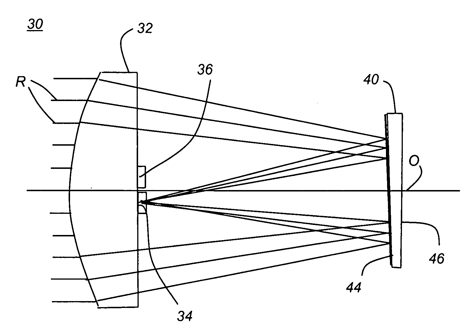
The present invention provides an apparatus for collecting and separating light from a polychromatic source. It includes a light concentrator for redirecting incident light, a spectral separator for separating light into different spectral bands, and two light receivers for receiving the separated bands. The invention allows for efficient concentration of light onto photoreceivers by directing light at small angles of incidence to the surface of the spectral separator. The technical effects of the invention include improved efficiency in concentrating and separating light, as well as improved performance of photoreceivers.

Problems solved by technology

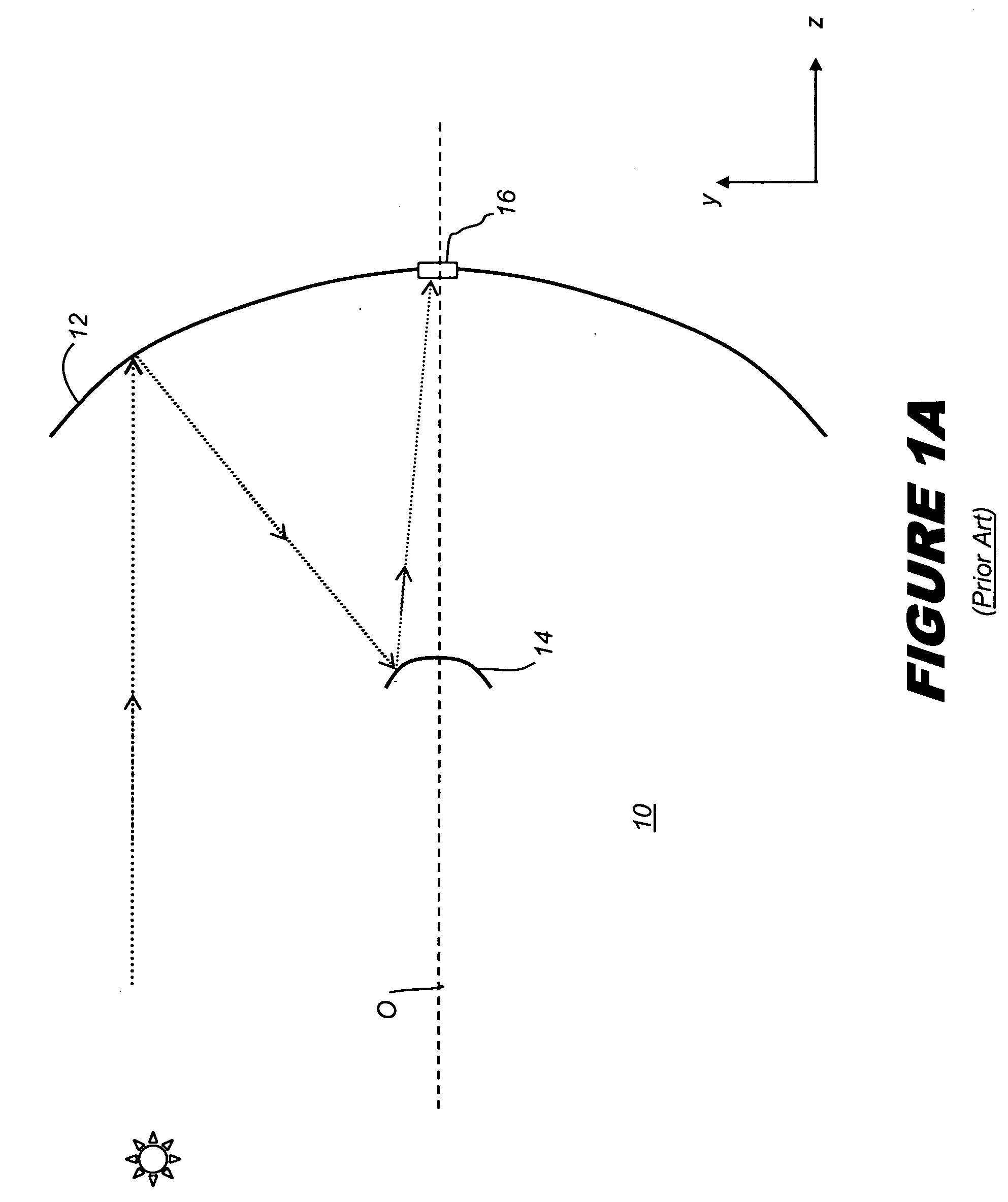
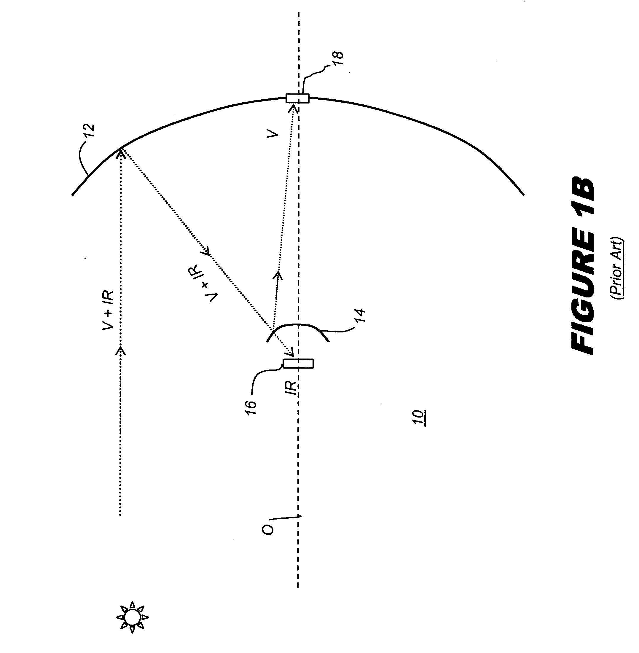
A recognized problem with this architecture, a problem inherent to the Cassegrain model, is that secondary mirror 14 presents an obstruction to on-axis light, so that a portion of the light, nominally as much as about 10%, does not reach primary mirror 12, reducing the overall light-gathering capability of photovoltaic apparatus 10.
While stacked photovoltaics can provide some measure of improvement in overall efficiency, these multilayered devices can be costly to fabricate.
There can also be restrictions on the types of materials that can be stacked together atop each other, making it difficult for such an approach to prove economical for a broad range of applications.
While the approach shown in the Fraas paper advantageously provides spectral separation and concentrates light using the same set of optical components, there are some significant limitations to the solution that it presents.
A first problem relates to the overall losses due to obstruction of the aperture, as were noted earlier.
As another problem, the apparatus described by Fraas et al. has a limited field of view of the sky because it has a high concentration in each axis due to its rotational symmetry.
Yet another drawback relates to the wide bandwidths of visible light provided to a single photovoltaic receiver.
With many types of photovoltaic materials commonly used for visible light, an appreciable amount of the light energy would still be wasted using such an approach, possibly resulting in excessive heat.
Where a dichroic coating is used with incident light at angles beyond about + / −20 degrees from normal, undesirable spectral effects can occur, so that spectral separation of light, due to variations in the angles of incidence, is compromised at such higher angles.
High incident angles of some portion of the light on this surface could render such a solution as less than satisfactory with respect to light efficiency.
However, as noted in the Imenes article cited above, the approach shown in the Soule '013 patent exhibits substantial optical losses.
Some of these losses relate to the high incident angles of light directed to the selective heat mirror that is used.
There are inherent problems with dichroic surface shape and placement for light focused from a parabolic mirror.
A flat dichroic surface positioned near the focal region of a parabolic reflector would exhibit poor separation performance for many designs, constraining the dimensions of a light collection system.
The lateral optical type of system exhibits good optical transmission levels but has relatively low efficiency.
This is at least partly due to a significant amount of spectral contamination resulting from the relatively high incident angles of light on the dichroic surface of beamsplitter 20.
Against obstacles such as poor dichroic surface response, conventional approaches have provided only a limited number of solutions for achieving, at the same time, both good spectral separation and efficient light flux concentration of each spectral component.
The Cassegrain model of FIGS. 1A and 1B can be optimized, but always presents an obstruction near the focal point of the primary mirror, and is thus inherently disadvantaged.
Solutions that employ dichroic separation perform best where incident light angles on the dichroic surface are low with respect to normal; however, as exemplified in FIG. 1C, many proposed designs do not appear to give enough consideration to these spectral separation characteristics, resulting in poor separation or misdirected light and reduced efficiency.

Method used


Image

  • Apparatus for obtaining radiant energy
  • Apparatus for obtaining radiant energy
  • Apparatus for obtaining radiant energy

Examples


Embodiment Construction

[0050] The present invention provides a light concentrator providing both enhanced spectral separation and a high degree of light flux concentration, exceeding the capabilities afforded by earlier approaches. The light concentrator of the present invention can be used as an optical component of a photovoltaic cell, embodied either as a discrete cell or as part of a photovoltaic cell array. While the apparatus of the present invention is well suited to photovoltaic applications, its utility is broader in scope, so that it can be used in any application where it is beneficial to obtain concentrated light energy that has been spectrally separated.

[0051] The term “light” as used in this disclosure broadly refers to radiant energy in the electromagnetic spectrum, with “polychromatic light” spanning wavelengths that include infrared light, visible light, and ultraviolet light. Throughout this specification, references are made to portions of the electromagnetic spectrum that have relativ...


PUM


Abstract

An apparatus for obtaining energy from a polychromatic radiant energy source has a light concentrator for concentrating and redirecting incident radiant energy, having an optical axis, and a spectral separator disposed along the optical axis, apart from the light concentrator and in the path of concentrated, redirected radiant energy. The spectral separator has a first planar surface treated to reflect a first spectral band of light toward a first focal region and to transmit a second spectral band and a second planar surface spaced apart from the first planar surface and oblique with respect to the first planar surface. The second planar surface is treated to reflect the second spectral band back through the first planar surface and toward a second focal region spaced apart from the first focal region. First and second light receivers are disposed nearest each respective focal region for receiving the first and second spectral bands.

Description

CROSS REFERENCE TO RELATED APPLICATIONS[0001] Reference is made to U.S. Provisional Patent Application Ser. No. 60 / 751810 entitled “Method and Apparatus for Concentrating Light” by Cobb et al. filed Dec. 19, 2005 (docket 19844). Reference is also made to U.S. Provisional Patent Application Ser. No. 60 / 778080 entitled “Light Collector and Concentrator” by Cobb et al. filed Feb. 28, 2006 (docket 19910).STATEMENT REGARDING FEDERALLY SPONSORED RESEARCH OR DEVELOPMENT [0002] This invention was made with government support under agreement w91 1nf-05-9-0005 awarded by the government. The government has certain rights in the invention.FIELD OF THE INVENTION [0003] This invention generally relates to apparatus for efficiently collecting and concentrating light, and more particularly relates to an apparatus that collects and separates light into two or more spectral bands, each directed toward a separate receiver. BACKGROUND OF THE INVENTION [0004] Efficient collection and concentration of ra...

Claims


Application Information

Patent Timeline
Patent Type & Authority Applications(United States)
IPC IPC(8): H02N6/00F24S23/00F24S23/79
CPCF24J2/06F24J2/18Y02E10/52H01L31/0547G02B19/0028H01L31/0549H01L31/0543G02B19/0042F24S23/00F24S23/79F24S50/20Y02E10/47G02B26/08G02B27/00G02B5/08
Inventor COBB, JOSHUA MONROEBRUNING, JOHN H.
Owner CORNING INC
Learn More