Hydrogen transport membrane fabrication method

a hydrogen transport membrane and fabrication method technology, applied in the direction of membranes, liquid/solution decomposition chemical coatings, separation processes, etc., can solve the problems of inability to obtain very thin layers of hydrogen transport materials, the diffusion resistance of hydrogen through the support is invariably increased, and the hydrogen diffusion resistance is greater than. to achieve the effect of preventing defects from forming

Inactive Publication Date: 2007-05-17
PRAXAIR TECH INC
View PDF13 Cites 11 Cited by
  • Summary
  • Abstract
  • Description
  • Claims
  • Application Information

AI Technical Summary

Benefits of technology

[0012] As can be appreciated, when the salt solution contacts the ceramic support, it only precipitates upon contact with the precipitating agent which is located in the pores. Thus, regions of the ceramic support located between pores are not coated at such time nor will the precipitated metal penetrate into the pores. Since the pores have been bridged, when the layer of hydrogen transport material is applied to the surface of the ceramic support, the metal bridging the pores will prevent defects from forming in the membrane and therefore, very thin layers of hydrogen transport material are able to be applied and while leaving the pores of the ceramic support in an open condition to allow for diffusion of the hydrogen through the ceramic support.

Problems solved by technology

A disadvantage of a membrane formed in a manner that involves filling the pores of a support with the hydrogen transport material is that the distance for the hydrogen to diffuse is greater than that possibly attainable with a thin metallic coating of material on the support.
Additionally, the diffusion resistance of the hydrogen through the support has invariably increased due to the plugging of the pores.
A problem with this technique is that it presents a limitation in the ability to obtain very thin layers of hydrogen transport materials.

Method used


Image

  • Hydrogen transport membrane fabrication method
  • Hydrogen transport membrane fabrication method
  • Hydrogen transport membrane fabrication method

Examples


Embodiment Construction

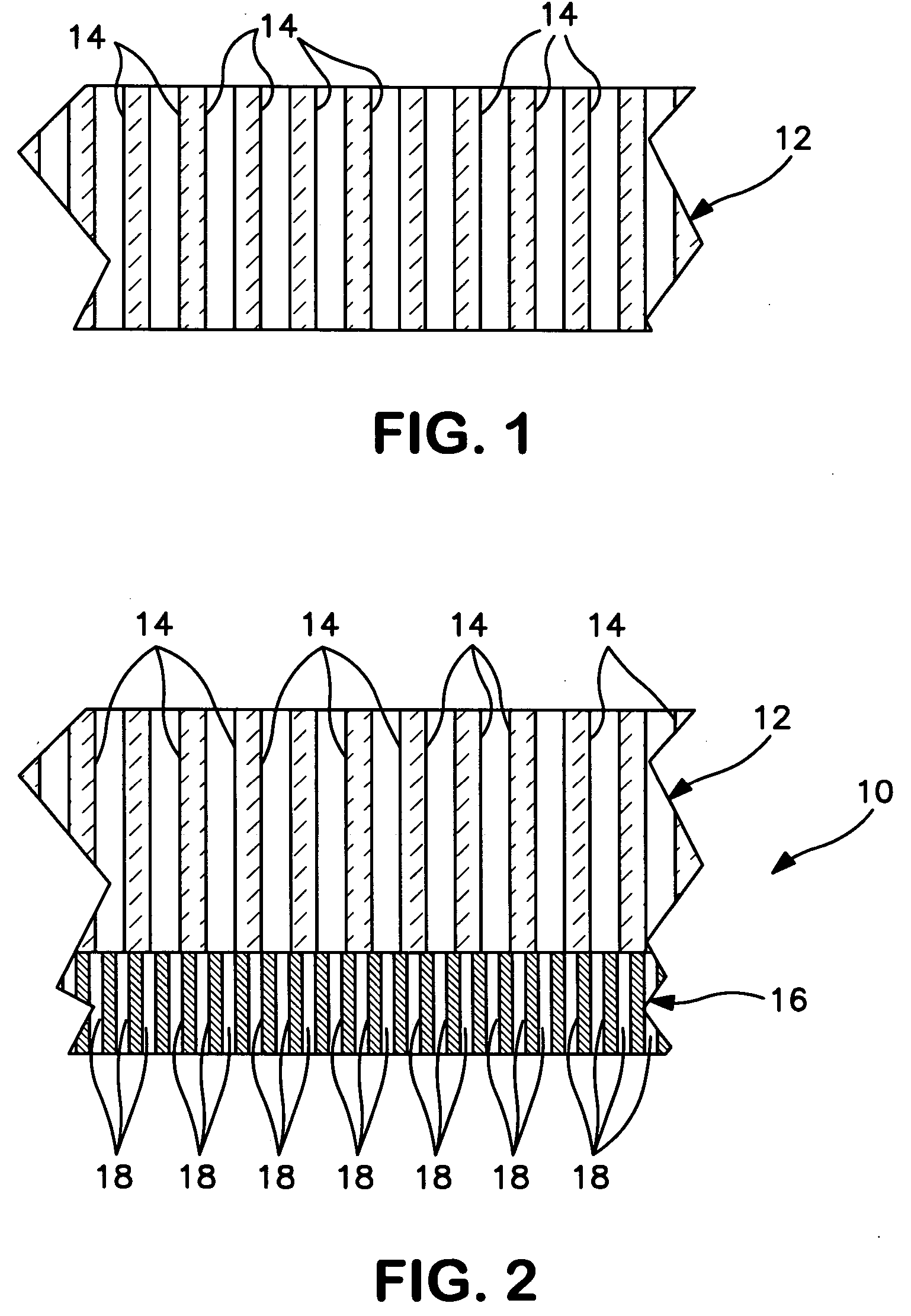
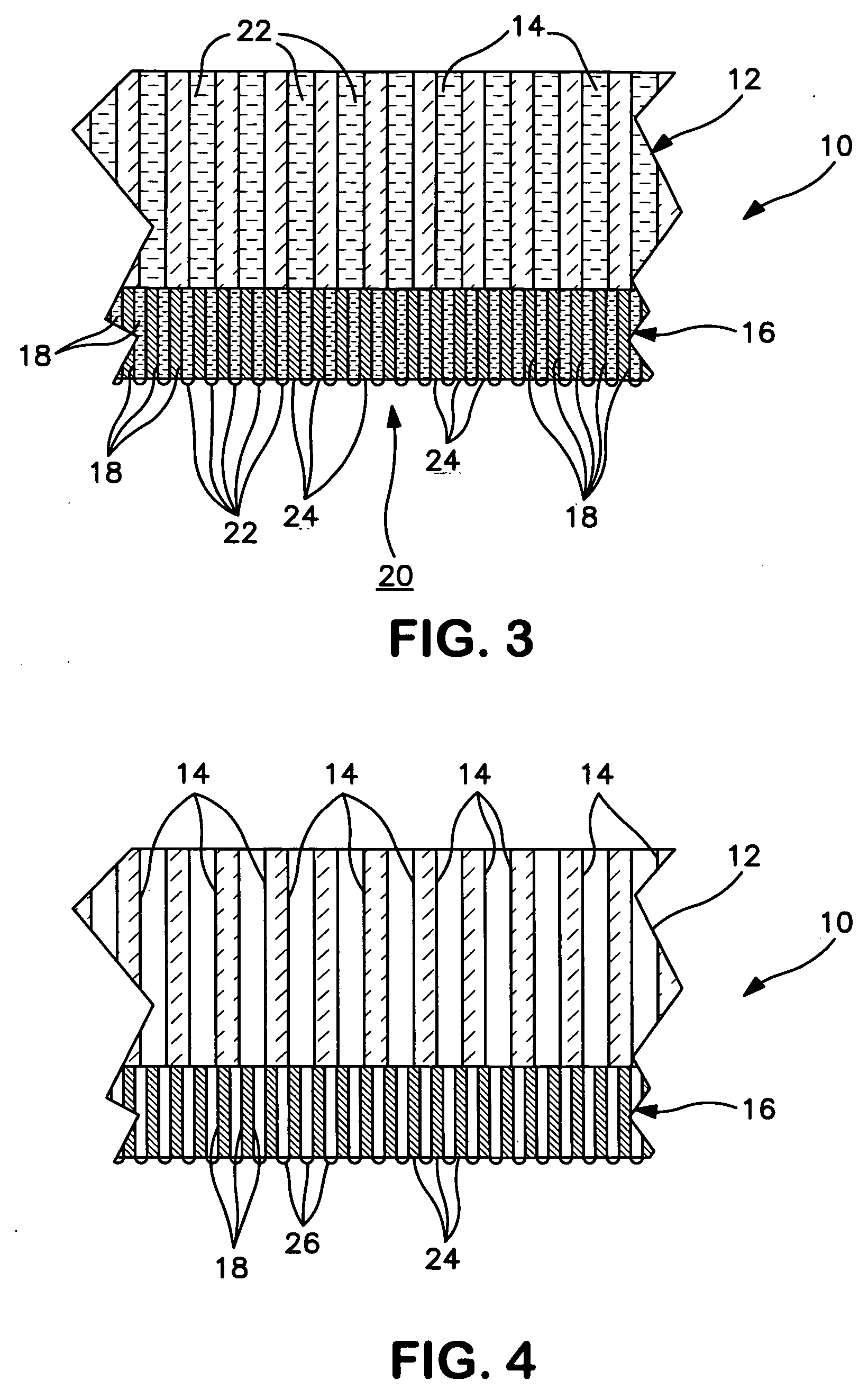
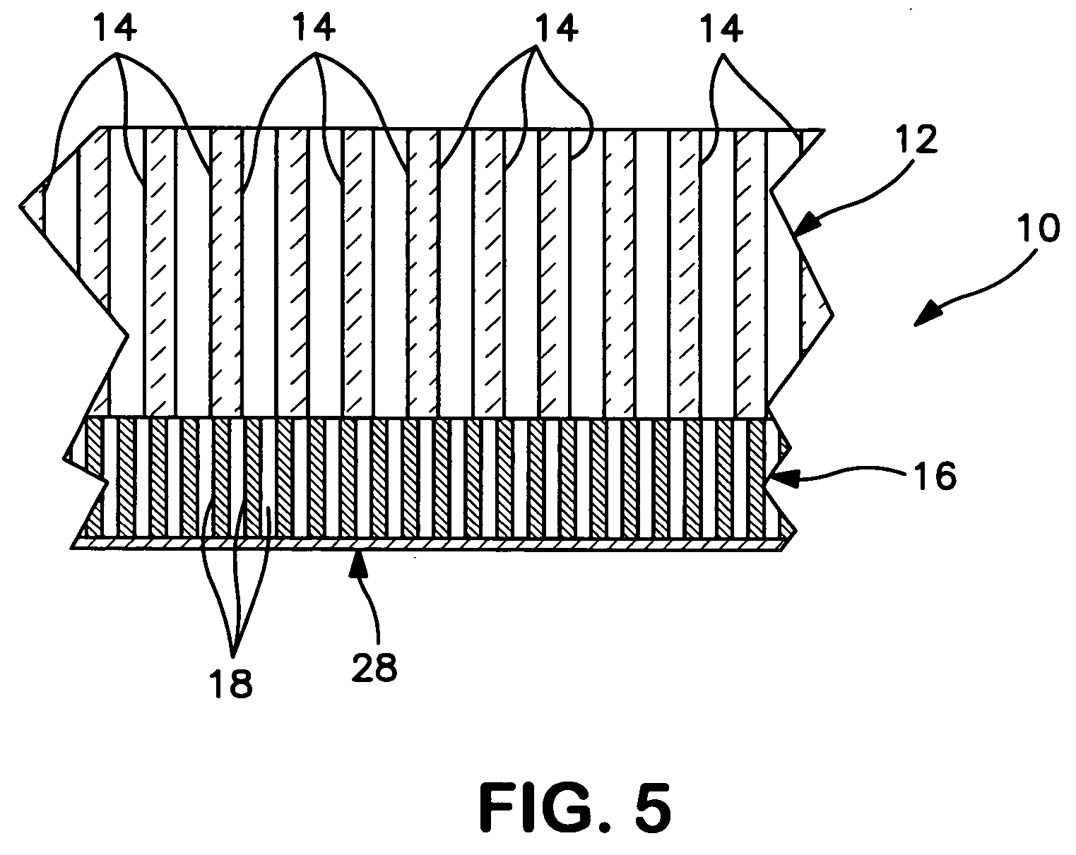
[0024] With reference to FIGS. 1 and 2, a hydrogen transport membrane is formed by first forming a porous ceramic support 10 that will be used in supporting a hydrogen transport material made up of palladium or an alloy of palladium. Porous support 10 is formed by first producing a first porous layer 12 having a first set of pores 14 and then forming a second porous layer 16 having a second set of pores 18 on the first porous layer 12. As shown in the illustration, the second set of pores 18 has a smaller pore size than first set of pores 14. This allows a large open area to be provided adjacent to the hydrogen transport material by virtue of the second porous layer 16 and an increased pore size of first porous layer 12 to minimize diffusion resistance of the hydrogen to be separated through the porous support 10.

[0025] It is to be noted that although first set of pores 14 and second set of pores 18 are shown as being cylindrical bores, preferably, the structure is an interconnecte...


PUM

PropertyMeasurementUnit
thicknessaaaaaaaaaa
pore sizeaaaaaaaaaa
pore sizeaaaaaaaaaa

Abstract

A method of forming a hydrogen transport membrane to separate hydrogen from a hydrogen containing feed in which a porous ceramic support is formed to support a dense layer of palladium or an alloy of palladium serving as a hydrogen transport material. Isolated deposits of palladium, a palladium alloy or a component of such alloy are produced on a surface of the porous ceramic support that bridge pores within the porous ceramic support without penetrating the pores and without bridging regions of the surface defined between the pores. The isolated deposits of the metal are produced by an electroless plating process that involves contacting the porous ceramic support with a precipitating agent so that the precipitating agent fills the pores but does not seep out of the pores onto the regions of the surfaces defined between the pores. The surface is then contacted with a salt solution containing a salt of the metal so that said metal precipitates and produces the isolated deposits of the metal. Thereafter, the dense layer is formed on the surface having the isolated deposits.

Description

FIELD OF THE INVENTION [0001] The present invention relates to a method of forming a hydrogen transport membrane having a thin layer of a hydrogen transport material, for example, palladium or an alloy of palladium, supported on a porous ceramic support. More particularly, the present invention relates to such a method in which prior to depositing the layer of hydrogen transport material on to the support, the hydrogen transport material or a component thereof is deposited on the support by an electroless plating process that is conducted to form deposits bridging the pores of the support without penetrating the pores and without being deposited onto regions of the support surrounding the pores. BACKGROUND OF THE INVENTION [0002] Composite hydrogen transport membranes are used to separate hydrogen from a hydrogen containing feed for a variety of industrial processes. Such membranes can consist of a hydrogen transport material supported by a porous support. It is believed that such m...

Claims


Application Information

Patent Timeline
Patent Type & Authority Applications(United States)
IPC IPC(8): B32B3/26B32B3/00B32B9/00B32B9/04
CPCB01D53/228B01D67/0069B01D69/10B01D71/022C01B3/505C23C18/1644Y10T428/24975C23C18/1658C23C18/1692C23C18/1889B01D2325/02B01D2325/023B01D2325/04C23C18/1651Y10T428/249953Y10T428/249981Y10T428/249987Y10T428/24999Y10T428/31504
Inventor APTE, PRASAD S.SCHWARTZ, JOSEPH MICHAELCALLAHAN, SHAWN W.
Owner PRAXAIR TECH INC
Why Eureka
Try Eureka