Photoemissive ion mobility spectrometry in ambient air

a technology of ion mobility and ionization chamber, which is applied in the field of ion mobility spectrometer, can solve the problems of low free electron count and sensitivity, and the possibility of photochemical reactions in the ionization chamber, so as to avoid the photochemical reactions of analytes, enhance the nitro-organic signal, and enhance the photo-emitted current

Inactive Publication Date: 2007-05-24
NORTH DAKOTA STATE UNIV RES FOUND
View PDF3 Cites 27 Cited by
  • Summary
  • Abstract
  • Description
  • Claims
  • Application Information

AI Technical Summary

Benefits of technology

[0016] Total internal reflection is incorporated for the backside illumination using optical elements such as a fused silica prism. This enhances the photo-emitted current by at least a factor of five and avoids photochemistry of the analytes by preventing the ultraviolet light from entering the gas flow region. A significant enhancement in the nitro-organic signal was observed using air as the carrier gas. The spectrometer of the present invention allows for the direct vaporization of adsorbed explosive molecules from surfaces followed by direct injection into the photoemissive ion mobility spectrometer through a heated inlet.
[0017] The photoemissive approach of the present invention creates the anions in the plane of a thin film metal coating in very large numbers without the electronic shutter grid losses. The shutter grid pulse width is one of the factors determining the resolution of a conventional linear IMS. Typical IMS shutter pulse widths are 50-500 μs. Because the photoemissive technique is expected to produce reactant ion pulse widths on the order of 20 μs, higher resolution than the conventional IMS is achievable.

Problems solved by technology

The Begley et al. device, however, used normal incidence illumination of the ionization source resulting in transmission of U.V. light into the ionization chamber, which lowers the free electron count and sensitivity and makes photochemical reactions in the ionization chamber likely.

Method used


Image

  • Photoemissive ion mobility spectrometry in ambient air
  • Photoemissive ion mobility spectrometry in ambient air
  • Photoemissive ion mobility spectrometry in ambient air

Examples


Embodiment Construction

[0049] Referring more specifically to the drawings, for illustrative purposes the present invention is embodied in the apparatus generally shown in FIG. 1 through FIG. 13. It will be appreciated that the apparatus may vary as to configuration and as to details of the parts, and that the method may vary as to the specific steps and sequence, without departing from the basic concepts as disclosed herein.

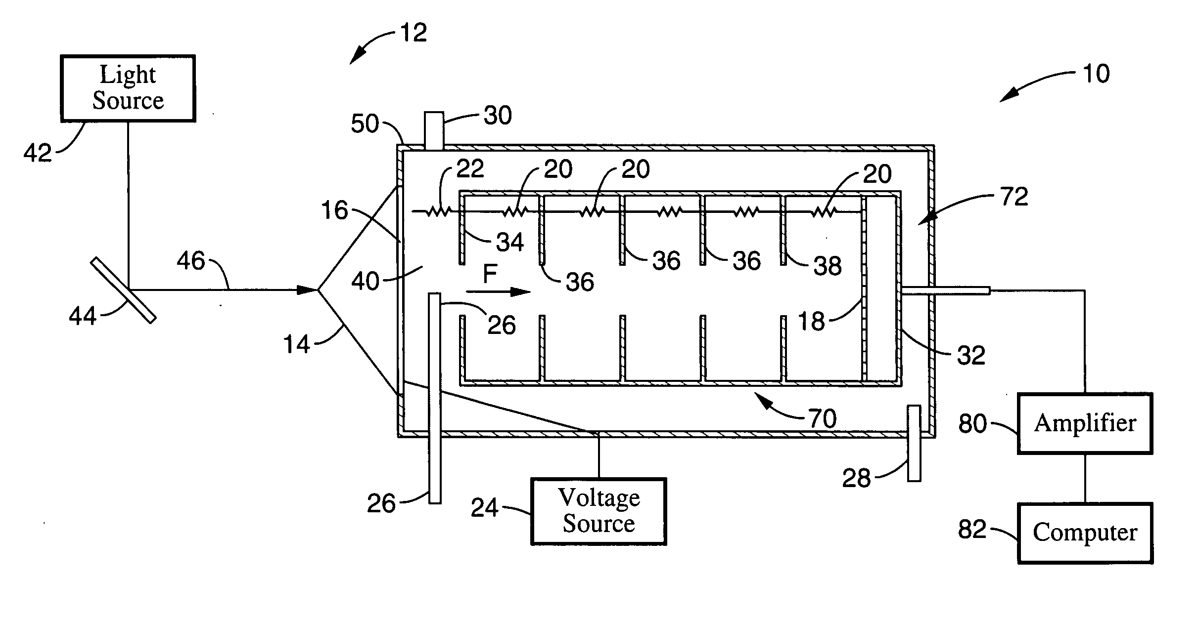
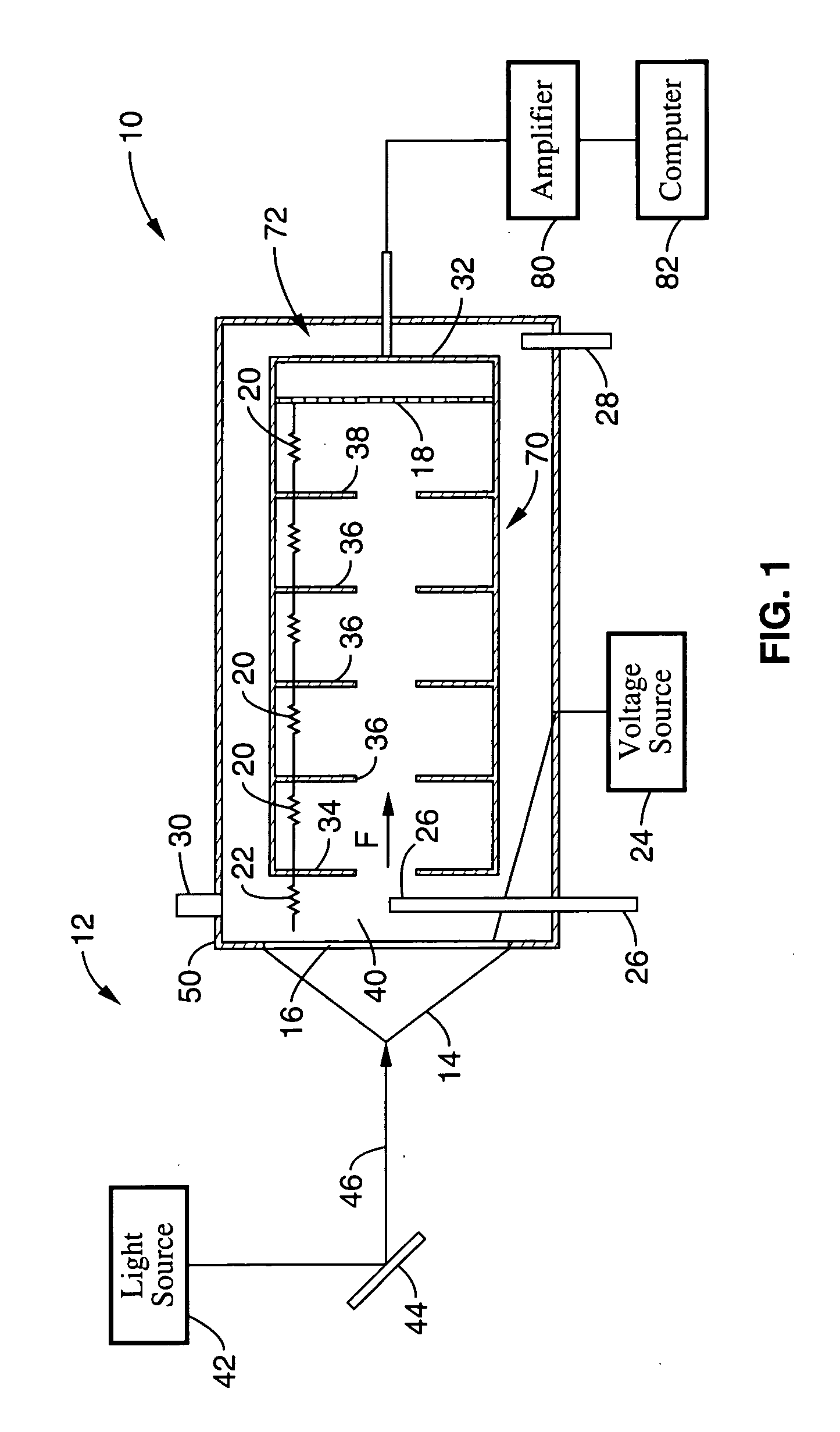
[0050]FIG. 1 illustrates a schematic diagram of a photoemissive ion mobility spectrometer 10 in accordance with the present invention. The IMS system is comprised of three main parts: (1) a photoemissive ionization source 12 for generation of free electrons; (2) a drift tube 70, for separation of ions; and (3) a detector 72 for detection of ions.

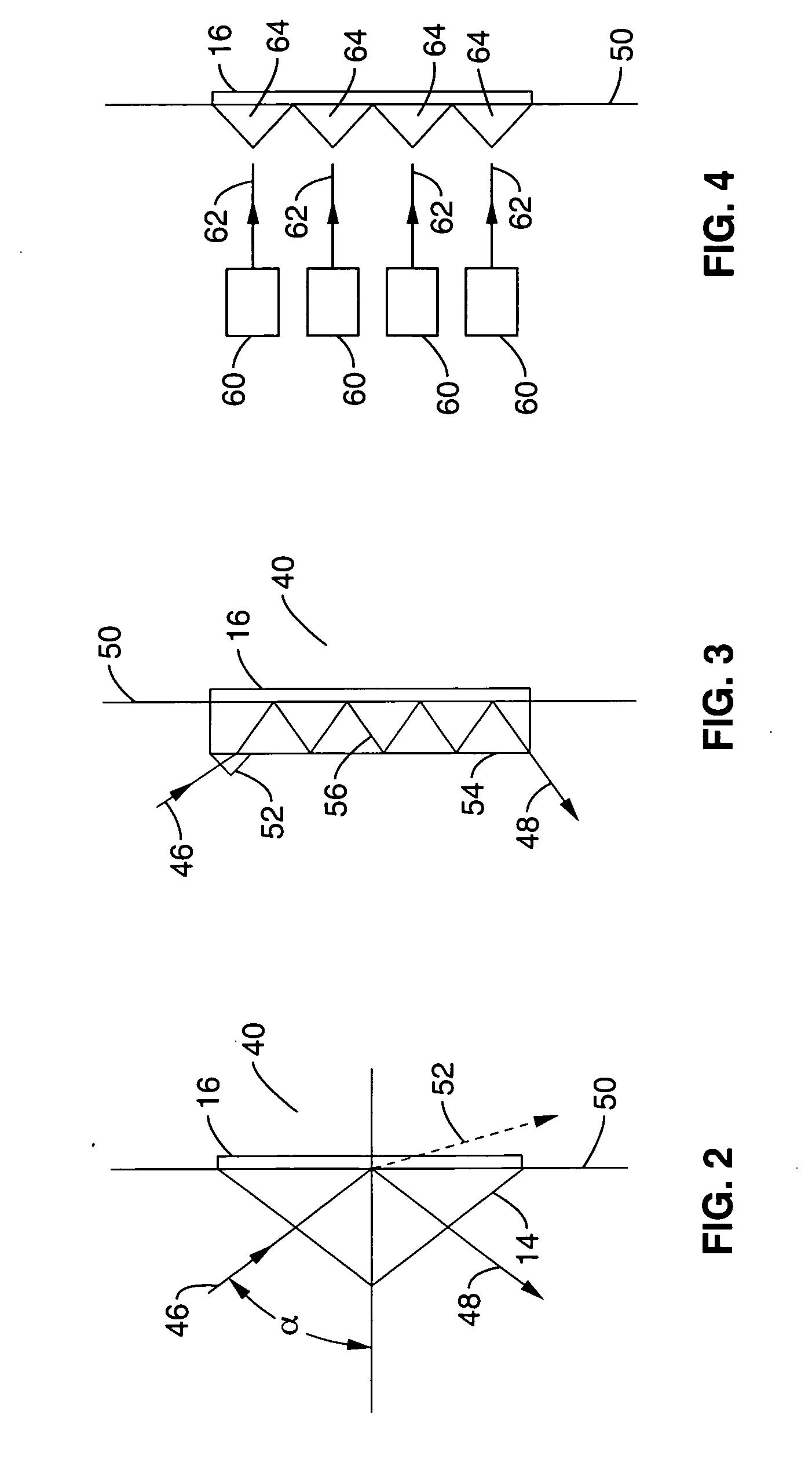
[0051] The photoemissive source 12 generally comprises a light source 42 that is configured to direct a beam of light 46 at optical element 14. The backside of optical element 14 has a metal coating or plating 16, which is positioned at the o...


PUM


Abstract

A photoemissive ion mobility spectrometer is disclosed for of chlorinated hydrocarbons and nitro-organic materials. Backside illumination of a thin gold film by pulsed laser radiation, pulsed ultraviolet xenon flashlamp, or like UV source, is used to produce bursts of low energy photo-emitted electrons. These swarms of thermalized electrons are directly attached by electronegative analytes or by reactant molecules, followed by charge transfer to the more electronegative analyte. Total internal reflection is incorporated for the backside illumination using optical elements such as a fused silica prism. The spectrometer allows for the direct vaporization of adsorbed explosive molecules from surfaces followed by direct injection into the photoemissive ion mobility spectrometer through a heated inlet.

Description

CROSS-REFERENCE TO RELATED APPLICATIONS [0001] This application claims priority from U.S. provisional application Ser. No. 60 / 701,603 filed on Jul. 21, 2005, incorporated herein by reference in its entirety.STATEMENT REGARDING FEDERALLY SPONSORED RESEARCH OR DEVELOPMENT [0002] This invention was made with Government support under Grant No. EPS-0083063, awarded by the National Science Foundation Experimental Program to Stimulate Competitive Research, and Contract No. F08637-98-C6009 through Dakota Technologies, Inc., supported by the Air Force Research Laboratory and the Strategic Environmental Development Program (SERDP). The Government has certain rights in this invention.INCORPORATION-BY-REFERENCE OF MATERIAL SUBMITTED ON A COMPACT DISC [0003] Not Applicable NOTICE OF MATERIAL SUBJECT TO COPYRIGHT PROTECTION [0004] A portion of the material in this patent document is subject to copyright protection under the copyright laws of the United States and of other countries. The owner of ...

Claims


Application Information

Patent Timeline
Patent Type & Authority Applications(United States)
IPC IPC(8): H01J49/00
CPCG01N27/622H01J49/08
Inventor SWENSON, ORVEN F.HONG, FENG
Owner NORTH DAKOTA STATE UNIV RES FOUND
Why Eureka
Try Eureka