Neurostimulation lead with concentric electrodes

Inactive Publication Date: 2007-05-24
PRAGER JOSHUA P
View PDF9 Cites 19 Cited by
  • Summary
  • Abstract
  • Description
  • Claims
  • Application Information

AI Technical Summary

Benefits of technology

[0017] Contacts may also be slightly curved to conform to the shape of the durra on which the lead will be placed. The concentric electrode pattern of the leads of this invention requires only two conductors, one for the anode and one for the cathode, to accomplish better the performance of the previous “pentode” configuration. Leads may be constructed with any desired number of concentric pairs of electrodes, ranging in number from one to eight such concentric pairs. Up to eight concentric electrode pairs may be coupled to currently available 16 channel (outputs) pulse generators. The concentric electrode pairs of this invention thus provide a significantly enhanced degree of freedom to the treating physician with regard to the design of effective stimulation therapy regimes.
[0018] The

Problems solved by technology

The usual target of stimulation is the spinal cord; thus, concurrent stimulation of the nerve root is regarded as undesirable.
It is know

Method used


Image

  • Neurostimulation lead with concentric electrodes
  • Neurostimulation lead with concentric electrodes

Examples


Embodiment Construction

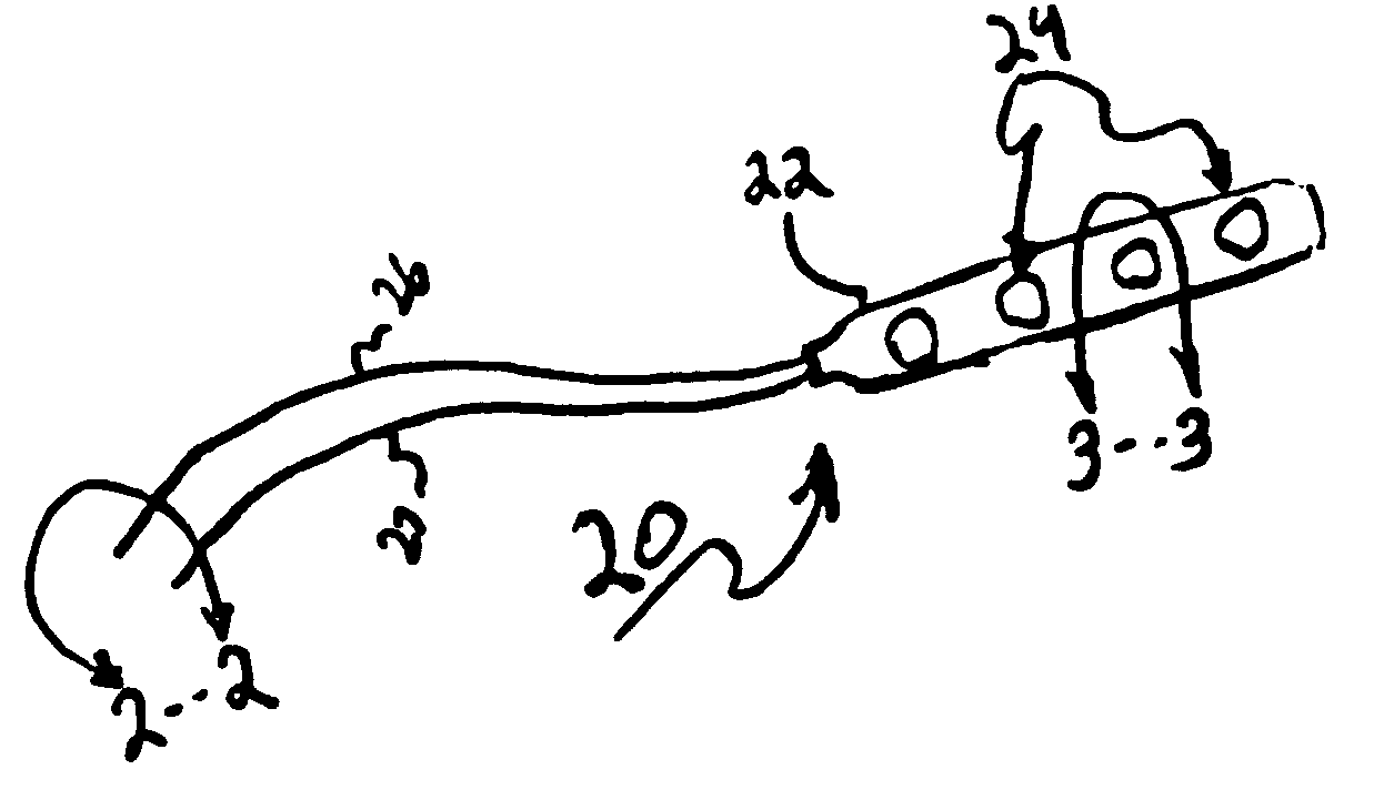
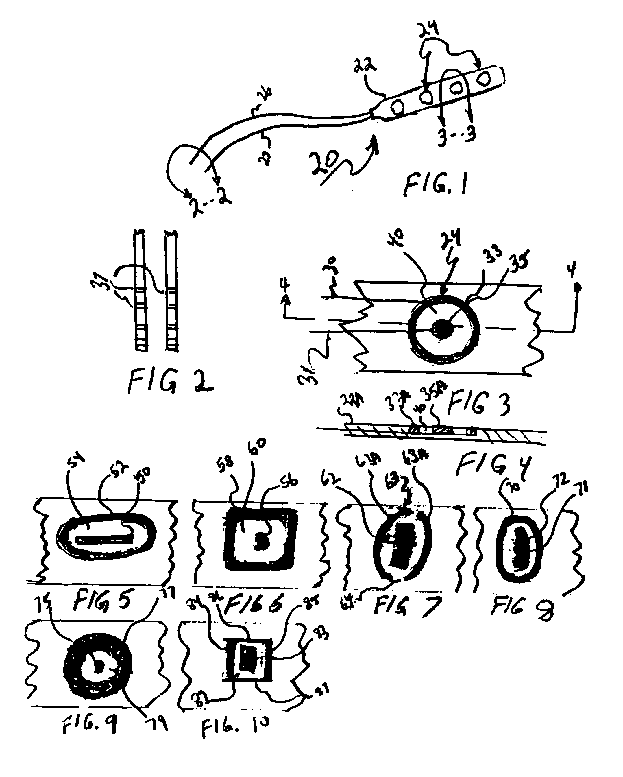
[0025] The surgical lead, generally 20, shown by FIG. 1 is constructed in accordance with current technology, and comprises a paddle-shaped flexible mounting base 22, carrying four electrode pairs, generally 24, of this invention. Two conductor cables 26, 27 extend from the base, and house fine wires 30, 31 (FIG. 3), which are conductively connected in conventional fashion to the anode 33 and cathode 35, respectively, of an electrode pair 24. As best shown by FIG. 2, each of the cables 26, 27, includes four wire conductors (e.g., 30, 31, FIG. 3), each individually terminating in a cylindrical electrical contact 37, adapted for plug-in connection to the output channels of a pulse generator in typical fashion. The lead of FIG. 1 is constructed with four electrode pairs 24, which require only half (eight) of the output contacts available in a 16 channel pulse generator to operate. Applying a voltage (conventionally in the millivolt range) between the electrodes 33, 35 induces a field w...


PUM


Abstract

A surgical lead for neurostimulation includes a central cathode circumscribed by an outer anode to define an annular space within which an electromagnetic field is generated between the two electrodes, and associated methods.

Description

CROSS-REFERENCE TO RELATED APPLICATION [0001] This application claims the benefit under 35 U.S.C. § 119 of U.S. patent application Ser. No. 60 / 734,624, filed Nov. 7, 2005 the contents of the entirety of which are incorporated by this reference.TECHNICAL FIELD [0002] This invention pertains to neurostimulation. It is particularly directed to the leads utilized in neurostimulation procedures, and provides an improved configuration for such leads. This disclosure is particularly directed to leads useful for spinal cord stimulation therapies, but those leads may also find application in brain stimulation therapies. BACKGROUND [0003] There are three generally recognized categories of neurostimulation; namely spinal cord stimulation (SCS); brain stimulation, subdivided into deep (DBS) and cortex stimulation, and peripheral nerve stimulation (PNS). [0004] Spinal cord stimulation involves placing a lead in the epidural space posterior to the spinal cord. Electromagnetic fields are induced b...

Claims


Application Information

Patent Timeline
IPC IPC(8): A61N1/05
CPCA61N1/0531A61N1/0534A61N1/0551A61N1/0553
Inventor PRAGER, JOSHUA P.
Owner PRAGER JOSHUA P
Why Eureka
Try Eureka