System and method for decreasing a rate of slag formation at predetermined locations in a boiler system

a technology of predetermined locations and slag formation, which is applied in the direction of solid fuel combustion, combustion control, lighting and heating apparatus, etc., can solve the problems of affecting the maintenance cycle of the boiler system, slag formation can dislodge from the walls, and damage equipment within the boiler system, so as to reduce the rate of slag formation, and increase the a/f ratio

Active Publication Date: 2007-05-31
GENERAL ELECTRIC CO
View PDF11 Cites 25 Cited by
  • Summary
  • Abstract
  • Description
  • Claims
  • Application Information

AI Technical Summary

Benefits of technology

[0008] A control system for decreasing a rate of slag formation in predetermined locations within a boiler system in accordance with another exemplary embodiment is provided. The boiler system has a first plurality of burners. The control system includes a plurality of temperature sensors disposed in the boiler system. The plurality of temperature sensors are configured to generate a first plurality of signals indicative of temperature levels at a first plurality of locations in the boiler system. The control system further includes a plurality of CO sensors disposed in the boiler system. The plurality of CO sensors are configured to generate a second plurality of signals indicative of CO levels at the first plurality of locations in the boiler system. The control system further includes a plurality of slag detection sensors disposed in the boiler system. The plurality of slag detection sensors are configured to generate a third plurality of signals indicative of slag thicknesses at the first plurality of locations in the boiler system. The control system further includes a controller operably coupled to the plurality of temperature sensors and to the plurality of CO sensors and the plurality of slag detection sensors. The controller is configured to determine a plurality of temperature levels at the first plurality of locations based on the first plurality of signals. The controller is further configured to determine a plurality of CO levels at the first plurality of locations based on the second plurality of signals. The controller is further configured to determine a plurality of slag thickness levels at the first plurality of locations based on the third plurality of signals. The controller is further configured to determine a second plurality of locations that have slag thickness levels greater than a threshold slag thickness level and temperature levels greater than a threshold temperature level and CO levels less than or equal to a threshold CO level. The second plurality of locations are a subset of the first plurality of locations. The controller is further configured to determine a second plurality of burners in the boiler system that are contributing to the second plurality of locations having slag thickness levels greater than the threshold slag thickness level and temperature levels greater than the threshold temperature level and CO levels less than or equal to the threshold CO level. The second plurality of burners are a subset of the first plurality of burners. The controller is further configured to decrease at least one of an A / F ratio of at least one burner of the second plurality of burners and an air-fuel mass flow to the at least one burner of the second plurality of burners, to decrease the rate of slag formation at the second plurality of locations.
[0009] A method for decreasing a rate of slag formation in predetermined locations within a boiler system in accordance with another exemplary embodiment is provided. The boiler system has a first plurality of burners, a plurality of slag detection sensors, a plurality of temperature sensors, and a plurality of CO sensors disposed therein. The method includes receiving a first plurality of signals from the plurality of temperature sensors disposed in the boiler system. The method further includes determining a plurality of temperature levels at a first plurality of locations in the boiler system based on the first plurality of signals. The method further includes receiving a second plurality of signals from the plurality of CO sensors disposed in the boiler system. The method further includes determining a plurality of CO levels at the first plurality of locations based on the second plurality of signals. The method further includes receiving a third plurality of signals from the plurality of slag detection sensors disposed in the boiler system. The method further includes determining a plurality of slag thickness levels at the first plurality of locations based on the third plurality of signals. The method further includes determining a second plurality of locations that have slag thickness levels greater than a threshold slag thickness level and temperature levels less than or equal to a threshold temperature level and CO levels greater than a threshold CO level. The second plurality of locations are a subset of the first plurality of locations. The method further includes determining a second plurality of burners in the boiler system that are contributing to the second plurality of locations having slag thickness levels greater than the threshold slag thickness level and temperature levels less than or equal to the threshold temperature level and CO levels greater than the threshold CO level. The second plurality of burners are a subset of the first plurality of burners. The method further includes increasing an A / F ratio of at least one burner of the second plurality of burners to decrease the rate of slag formation at the second plurality of locations.
[0010] A control system for decreasing a rate of slag formation in predetermined locations within a boiler system in accordance with another exemplary embodiment is provided. The boiler system has a first plurality of burners. The control system includes a plurality of temperature sensors disposed in the boiler system. The plurality of temperature sensors are configured to generate a first plurality of signals indicative of temperature levels at a first plurality of locations in the boiler system. The control system further includes a plurality of CO sensors disposed in the boiler system. The plurality of CO sensors are configured to generate a second plurality of signals indicative of CO levels at the first plurality of locations in the boiler system. The control system further includes a plurality of slag detection sensors disposed in the boiler system. The plurality of slag detection sensors are configured to generate a third plurality of signals indicative of slag thicknesses at the first plurality of locations in the boiler system. The control system further includes a controller operably coupled to the plurality of temperature sensors and to the plurality of CO sensors and the plurality of slag detection sensors. The controller is configured to determine a plurality of temperature levels at the first plurality of locations based on the first plurality of signals. The controller is further configured to determine a plurality of CO levels at the first plurality of locations based on the second plurality of signals. The controller is further configured to determine a plurality of slag thickness levels at the first plurality of locations based on the third plurality of signals. The controller is further configured to determine a second plurality of locations that have slag thickness levels greater than a threshold slag thickness level and temperature levels less than or equal to a threshold temperature level and CO levels greater than a threshold CO level. The second plurality of locations are a subset of the first plurality of locations. The controller is further configured to determine a second plurality of burners in the boiler system that are contributing to the second plurality of locations having slag thickness levels greater than the threshold slag thickness level and temperature levels less than or equal to the threshold temperature level and CO levels greater than the threshold CO level. The second plurality of burners are a subset of the first plurality of burners. The controller is further configured to increase an A / F ratio of at least one burner of the second plurality of burners to decrease the rate of slag formation at the second plurality of locations.
[0011] A method for decreasing a rate of slag formation in predetermined locations within a boiler system in accordance with another exemplary embodiment is provided. The boiler system has a first plurality of burners, a plurality of slag detection sensors, a plurality of temperature sensors, and a plurality of CO sensors disposed therein. The method includes receiving a first plurality of signals from the plurality of temperature sensors disposed in the boiler system. The method further includes determining a plurality of temperature levels at a first plurality of locations in the boiler system based on the first plurality of signals. The method further includes receiving a second plurality of signals from the plurality of CO sensors disposed in the boiler system. The method further includes determining a plurality of CO levels at the first plurality of locations based on the second plurality of signals. The method further includes receiving a third plurality of signals from the plurality of slag detection sensors disposed in the boiler system. The method further includes determining a plurality of slag thickness levels at the first plurality of locations based on the third plurality of signals. The method further includes determining a second plurality of locations that have slag thickness levels greater than a threshold slag thickness level and temperature levels less than or equal to a threshold temperature level and CO levels less than or equal to a threshold CO level. The second plurality of locations are a subset of the first plurality of locations. The method further includes determining a second plurality of burners in the boiler system that are contributing to the second plurality of locations having slag thickness levels greater than the threshold slag thickness level and temperature levels less than or equal to the threshold temperature level and CO levels less than or equal to the threshold CO level. The second plurality of burners are a subset of the first plurality of burners. The method further includes decreasing at least one of an air-fuel mass flow to the least one burner of the second plurality of burners and a fuel mass flow to the at least one burner of the second plurality of burners, to decrease the rate of slag formation at the second plurality of locations.
[0012] A control system for decreasing a rate of slag formation in predetermined locations within a boiler system in accordance with another exemplary embodiment is provided. The boiler system has a first plurality of burners. The control system includes a plurality of temperature sensors disposed in the boiler system. The plurality of temperature sensors are configured to generate a first plurality of signals indicative of temperature levels at a first plurality of locations in the boiler system. The control system further includes a plurality of CO sensors disposed in the boiler system. The plurality of CO sensors are configured to generate a second plurality of signals indicative of CO levels at the first plurality of locations in the boiler system. The control system further includes a plurality of slag detection sensors disposed in the boiler system. The plurality of slag detection sensors are configured to generate a third plurality of signals indicative of slag thicknesses at the first plurality of locations in the boiler system. The control system further includes a controller operably coupled to the plurality of temperature sensors and to the plurality of CO sensors and the plurality of slag detection sensors. The controller is configured to determine a plurality of temperature levels at the first plurality of locations based on the first plurality of signals. The controller is further configured to determine a plurality of CO levels at the first plurality of locations based on the second plurality of signals. The controller is further configured to determine a plurality of slag thickness levels at the first plurality of locations based on the third plurality of signals. The controller is further configured to determine a second plurality of locations that have slag thickness levels greater than a threshold slag thickness level and temperature levels less than or equal to a threshold temperature level and CO levels less than or equal to a threshold CO level. The second plurality of locations are a subset of the first plurality of locations. The controller is further configured to determine a second plurality of burners in the boiler system that are contributing to the second plurality of locations having slag thickness levels greater than the threshold slag thickness level and temperature levels less than or equal to the threshold temperature level and CO levels less than or equal to the threshold CO level. The second plurality of burners are a subset of the first plurality of burners. The controller is further configured to decrease at least one of an air-fuel mass flow to the least one burner of the second plurality of burners and a fuel mass flow to the least one burner of the second plurality of burners, to decrease the rate of slag formation at the second plurality of locations.
[0013] A method for decreasing a rate of slag formation in predetermined locations within a boiler system in accordance with another exemplary embodiment is provided. The boiler system has a first plurality of burners and a plurality of slag detection sensors. The method includes receiving a first plurality of signals from the plurality of slag detection sensors disposed in the boiler system. The method further includes determining a plurality of slag thickness levels at a first plurality of locations in the boiler system based on the first plurality of signals. The method further includes determining a second plurality of locations in the boiler system that have slag thickness levels greater than a threshold slag thickness level. The second plurality of locations are a subset of the first plurality of locations. The method further includes determining a second plurality of burners in the boiler system that are contributing to the second plurality of locations having slag thickness levels greater than the threshold slag thickness level. The second plurality of burners are a subset of the first plurality of burners. The method further includes delivering a slag reducing compound to the second plurality of burners for decreasing the rate of slag formation at the second plurality of locations.

Problems solved by technology

A problem associated with the foregoing boiler system is that the boiler system can have spatial regions or locations where slag or unburnt hydrocarbons begin to adhere to walls of the boiler system.
When slag formations become relatively thick, the slag formations can dislodge from the walls and damage equipment within the boiler system.
This slag formation, if not timely controlled, thus affects the maintenance cycle of the boiler system by causing an early costly cleanup operation.
This in turn adversely affects the power generation sales due to the resultant downtime.
At the same time, these slag formations reduce the heat transfer coefficient (capability) at these locations in a superheat and reheat zone since it reduces the overall thermal efficiency of the boiler system, increasing an operational cost of the boiler system for power generation.

Method used


Image

  • System and method for decreasing a rate of slag formation at predetermined locations in a boiler system
  • System and method for decreasing a rate of slag formation at predetermined locations in a boiler system
  • System and method for decreasing a rate of slag formation at predetermined locations in a boiler system

Examples


Embodiment Construction

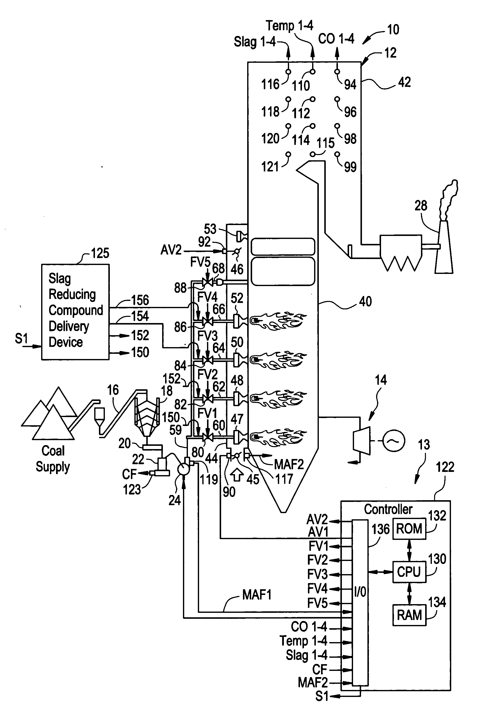
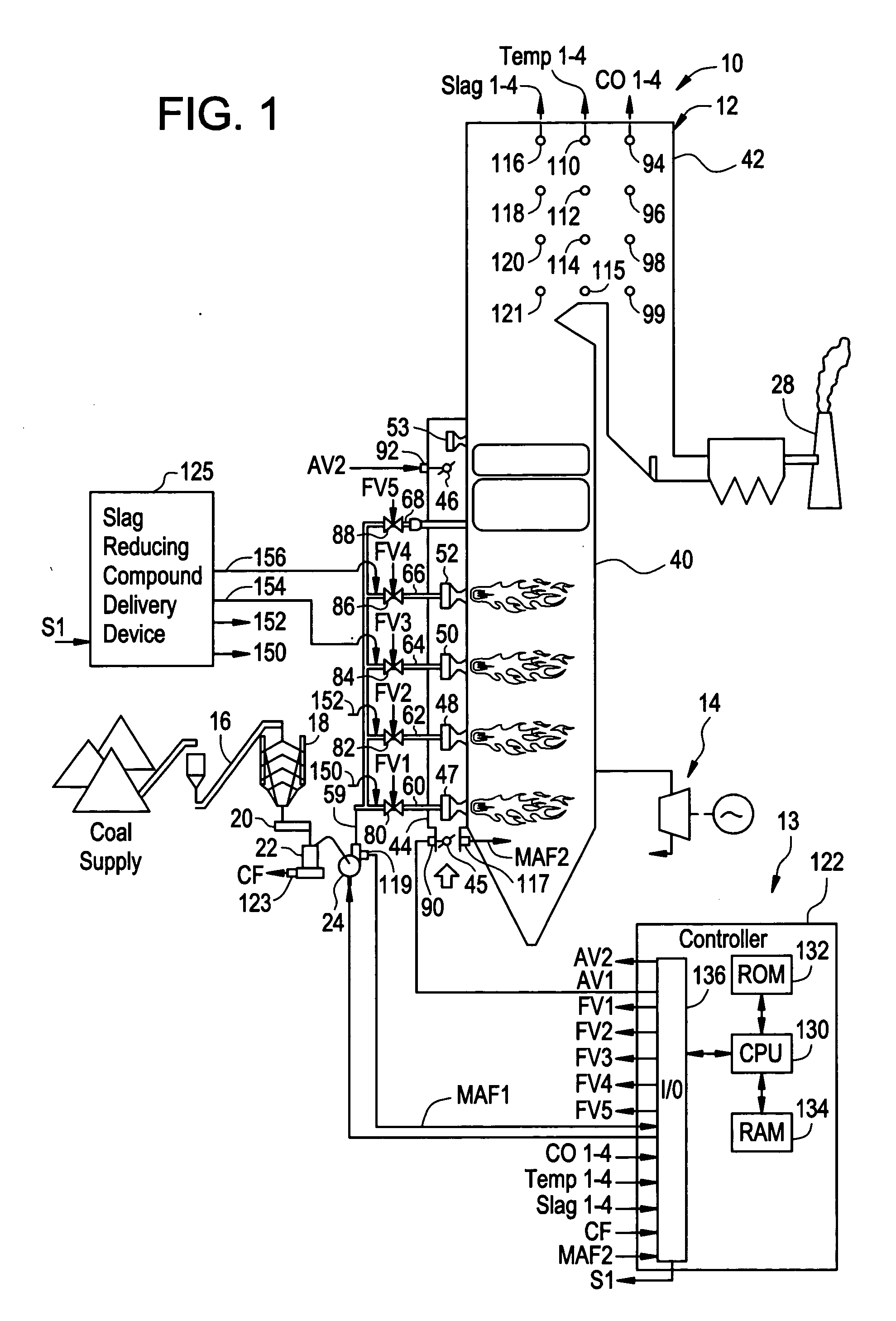
[0020] Referring to FIG. 1, a power generation system 10 for generating electrical power is illustrated. The power generation system 10 includes a boiler system 12, a control system 13, a turbine generator 14, a conveyor 16, a silo 18, a coal feeder 20, a coal pulverizer 22, an air source 24, and a smokestack 28.

[0021] The boiler system 12 is provided to burn an air-coal mixture to heat water to generate steam therefrom. The steam is utilized to drive the turbine generator 14, which generates electricity. It should be noted that in an alternative embodiment, the boiler system 12 could utilize other types of fuels, instead of coal, to heat water to generate steam therefrom. For example, the boiler system 12 could utilize any conventional type of hydrocarbon fuel such as gasoline, diesel fuel, oil, natural gas, propane, or the like. The boiler system 12 includes a furnace 40 coupled to a back path portion 42, an air intake manifold 44, burners 47, 48, 50, 52, an air port 53, and cond...


PUM


Abstract

A system and a method for decreasing a rate of slag formation at predetermined locations in a boiler system are provided. The boiler system has a plurality of burners, a plurality of slag detection sensors, a plurality of temperature sensors and a plurality of CO sensors disposed therein. The system determines locations within the boiler system that have relatively high slag thickness levels utilizing the plurality of slag detection sensors and then adjusts A/F ratios or mass flows of burners affecting those locations, or adds slag reducing additives to the burners affecting those locations, to decrease a rate of slag formation at the locations, utilizing signals from the plurality of slag detection sensor, the plurality of temperature sensors, and the plurality of CO sensors.

Description

CROSS REFERENCE TO RELATED APPLICATIONS [0001] This application is related to the following U.S. patent applications filed contemporaneously herewith: SYSTEM, METHOD, AND ARTICLE OF MANUFACTURE FOR ADJUSTING TEMPERATURE LEVELS AT PREDETERMINED LOCATIONS IN A BOILER SYSTEM, Attorney Docket No. 185126; and SYSTEM, METHOD, AND ARTICLE OF MANUFACTURE FOR ADJUSTING CO EMISSION LEVELS AT PREDETERMINED LOCATIONS IN A BOILER SYSTEM, Attorney Docket No. 170592, which are incorporated by reference herein in their entirety.BACKGROUND OF THE INVENTION [0002] Fossil-fuel fired boiler systems have been utilized for generating electricity. One type of fossil-fuel fired boiler system combusts an air / coal mixture to generate heat energy that increases a temperature of water to produce steam. The steam is utilized to drive a turbine generator that outputs electrical power. [0003] A problem associated with the foregoing boiler system is that the boiler system can have spatial regions or locations wher...

Claims


Application Information

Patent Timeline
Patent Type & Authority Applications(United States)
IPC IPC(8): F23B90/00F23N5/00
CPCF22B35/00F23J3/00F23J7/00F23K2201/505F23N1/022F23N5/003F23N2037/02F23N2041/10F23N2237/02F23N2241/10
Inventor WIDMER, NEILTAWARE, AVINASH
Owner GENERAL ELECTRIC CO
Why Eureka
Try Eureka