Electrostatic transducer, driving circuit of capacitive load, method for setting circuit constant, ultrasonic speaker, display device and directional acoustic system

Inactive Publication Date: 2007-05-31
SEIKO EPSON CORP
View PDF3 Cites 18 Cited by
  • Summary
  • Abstract
  • Description
  • Claims
  • Application Information

AI Technical Summary

Benefits of technology

[0015] An advantage of some aspects of the invention is to provide an electrostatic transducer, a method for setting a circuit constant, an ultrasonic speaker, a display device having the ultrasonic speaker, and a directional acoustic system, which are capable of reducing a driving power of the electrostatic transducer and ensuring a

Problems solved by technology

Accordingly, in the ultrasonic speaker using the piezoelectric transducer, a reproducible frequency band is narrow and thus reproduction quality deteriorates compared with a loudspeaker.
Accordingly, the reproduction quality of the ultrasonic speaker deteriorates.
Accordingly, in order to significantly shift the resonance frequency band of a circuit from the driving frequency band to a high frequency band, a coil inductance of the output transformer must be very small and this is not realistic.
The coil inductance value of the output transformer and the capacitance value of the electrostatic transducer are restricted within realistic ranges due to a structural limit.
However, since the configuration of the ultrasonic transducer in the related art is premised on the driving of the piezoelectric element, a problem may occur when the configuration applies to the driving of the electrostatic transducer.
Accordingly, when the circuit configuration disclosed in JP-A-2001-86587 applies to the electrostatic transducer, an external resistor having a relatively high resistance value must be added in order to obtain the flat pass band characteristic and thus un

Method used


Image

  • Electrostatic transducer, driving circuit of capacitive load, method for setting circuit constant, ultrasonic speaker, display device and directional acoustic system
  • Electrostatic transducer, driving circuit of capacitive load, method for setting circuit constant, ultrasonic speaker, display device and directional acoustic system
  • Electrostatic transducer, driving circuit of capacitive load, method for setting circuit constant, ultrasonic speaker, display device and directional acoustic system

Examples


Embodiment Construction

Description of Driving Circuit of Electrostatic Transducer According to the Invention:

[0131] First, a driving circuit of an electrostatic transducer (capacitive load) according to the invention will be described.

[0132] The electrostatic transducer according to the invention has three points.

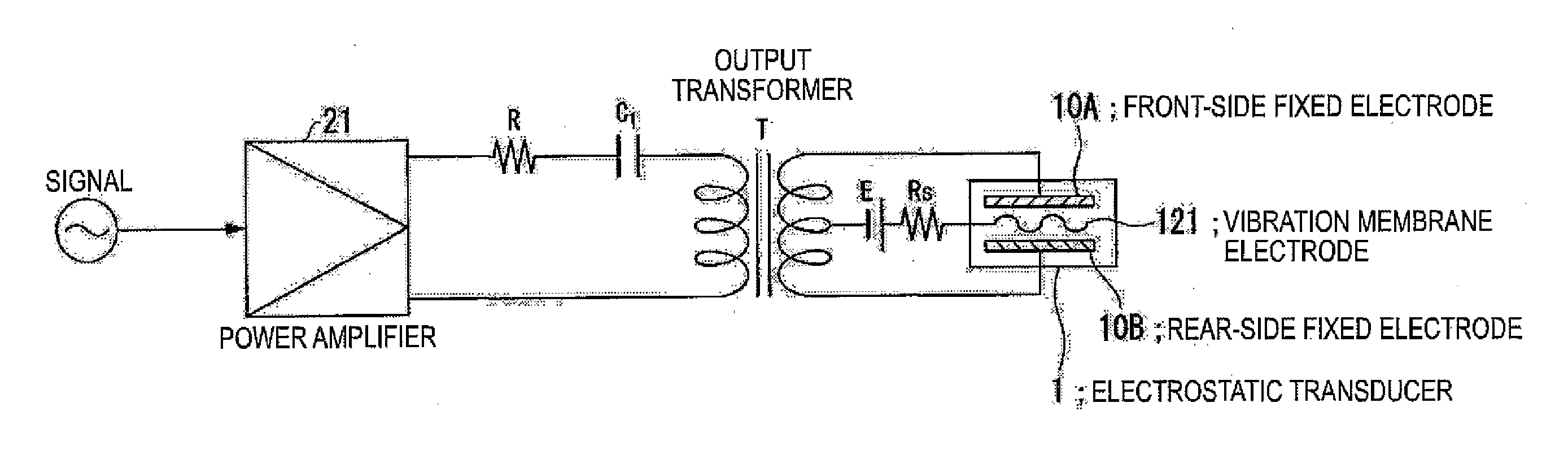
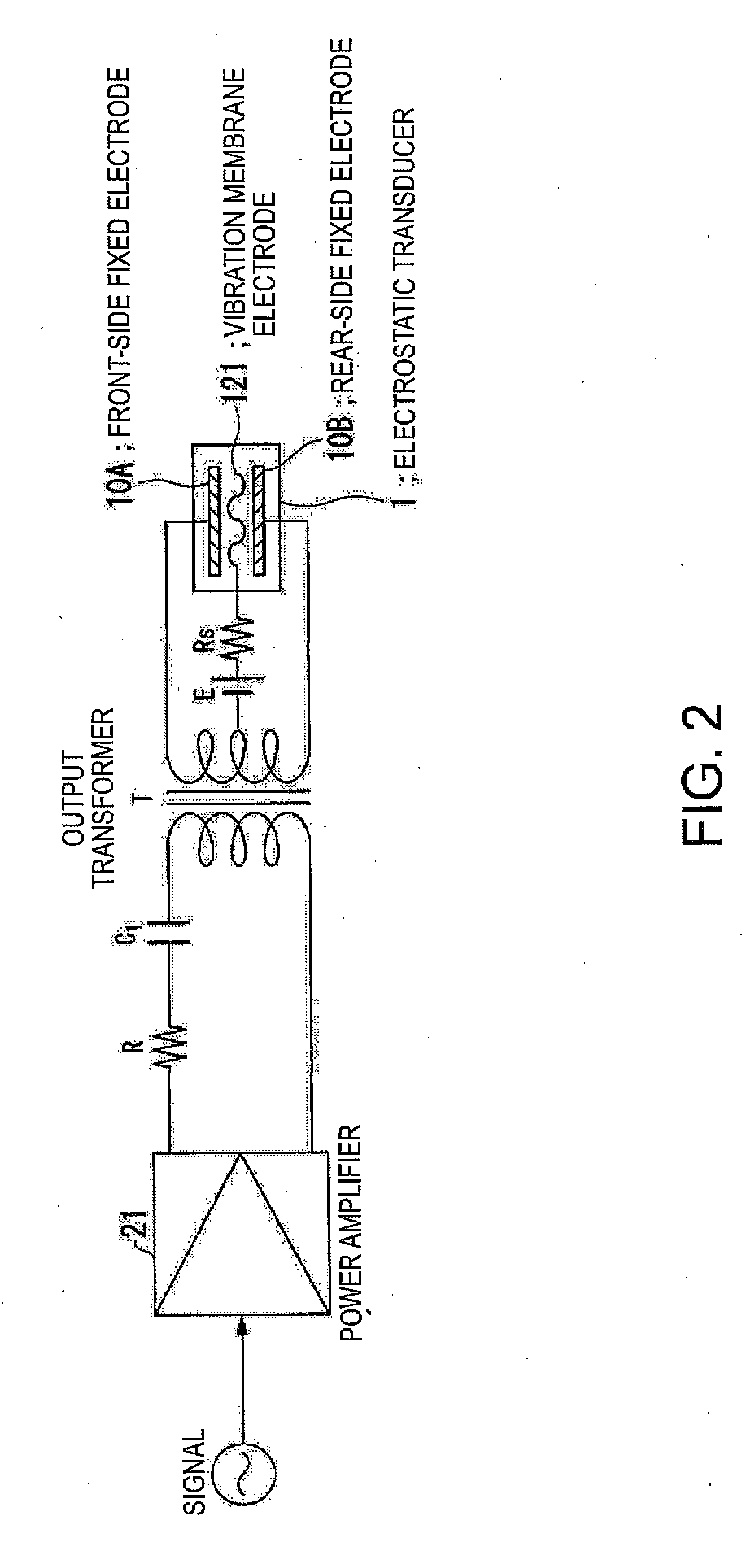
[0133] In a first point, a signal is applied to the electrostatic transducer by an output transformer to perform boosting and impedance-conversion of the signal by the output transformer. Accordingly, it is possible to obtain a high output sound pressure.

[0134] In a second point, a constant of the transformer is set (designed) such that a resonance frequency band of a resonance circuit formed by the output transformer and a load capacitance (electrostatic transducer) is matched to a carrier wave frequency band of the electrostatic transducer. Accordingly, since impedance of a load side in the vicinity of the carrier wave frequency increases, it is possible to reduce the power consumption in ...


PUM


Abstract

Provided is an electrostatic transducer which is driven by a boosted driving signal by boosting a modulated signal obtained by modulating a carrier wave with an acoustic signal in an audio frequency band, the transducer including: an output transformer T which connects the electrostatic transducer to a secondary side winding thereof in parallel and boosts the modulated signal; and a resistor R and a coupling capacitance C1 connected in series to a primary side winding of the output transformer T, wherein a circuit constant of a primary side circuit of the output transformer T including a serial circuit of the resistor R and the coupling capacitance C1 and a circuit constant of a secondary side circuit of the output transformer including a self-inductance L2 and a load capacitance CL of the secondary side winding of the output transformer T are set such that a resonance frequency f0 of a circuit formed by the self-inductance L2 of the secondary side winding of the output transformer T and the load capacitance CL of the electrostatic transducer is matched or approximately matched to a carrier wave frequency fc of the electrostatic transducer.

Description

BACKGROUND [0001] 1. Technical Field [0002] The present invention relates to an electrostatic transducer, and more particularly, to an electrostatic transducer for reproducing sound having sharp directivity by outputting a modulated wave obtained by modulating a carrier wave in an ultrasonic band with an acoustic signal in an audio frequency band, an ultrasonic speaker using the electrostatic transducer, a display device having the ultrasonic speaker, a directional acoustic system, and a driving circuit of a capacitive load. [0003] 2. Related Art [0004] An ultrasonic speaker can reproduce sound having sharp directivity by outputting a modulated wave obtained by modulating a carrier wave in an ultrasonic band with an acoustic signal in audio frequency band. In a transducer (transmitter) of the ultrasonic speaker, a piezoelectric transducer is generally used. However, since the piezoelectric transducer uses a sharp resonance characteristic, a sound pressure is high, but a frequency ba...

Claims


Application Information

Patent Timeline
IPC IPC(8): H04R3/00G03B31/00
CPCH04R3/00
Inventor MAYAZAKI, SHINICHI
Owner SEIKO EPSON CORP
Why Eureka
Try Eureka