System for detecting fluid changes and sensoring devices therefor

a technology of fluid change and sensor, applied in the field of detection, can solve the problems of blood collection and clot (hematoma), patient does not remember, and the head injury may have been so minor, and achieve the effect of reducing sensitivity

Active Publication Date: 2007-05-31
BAYER HEALTHCARE LLC
View PDF11 Cites 48 Cited by
  • Summary
  • Abstract
  • Description
  • Claims
  • Application Information

AI Technical Summary

Benefits of technology

[0038] In a further aspect, the present invention provides a method of sensing a change in fluid level in living tissue in a patient including: placing a first antenna pair in contact with the patient, the first antenna pair including a first transmitting antenna and a first receiving antenna; and placing a second antenna

Problems solved by technology

Moreover, bleeding (hemorrhage) can cause blood to collect and clot (hematoma).
Such a head injury may have been so minor that the patient does not remember it.
It is often difficult to detect hematomas, particularly when the hematoma occurs well after the time of an injury.
Extravasation can be caused, for example, by rupture or dissection of fragile vasculature, valve disease, inappropriate needle placement, or patient movement resulting in the infusing needle being pulled from the intended vessel or causing the needle to be pushed through the wall of the vessel.
High injection pressures and/or rates of some modern procedures can increase the risk of extravasation.
Extravasation can cause serious injury to patients.
In that regard, certain injection fluids such as contrast media or chemotherapy drugs can be toxic to tissue.
Unfortunately, each of these automated methods of

Method used


Image

  • System for detecting fluid changes and sensoring devices therefor
  • System for detecting fluid changes and sensoring devices therefor
  • System for detecting fluid changes and sensoring devices therefor

Examples


Embodiment Construction

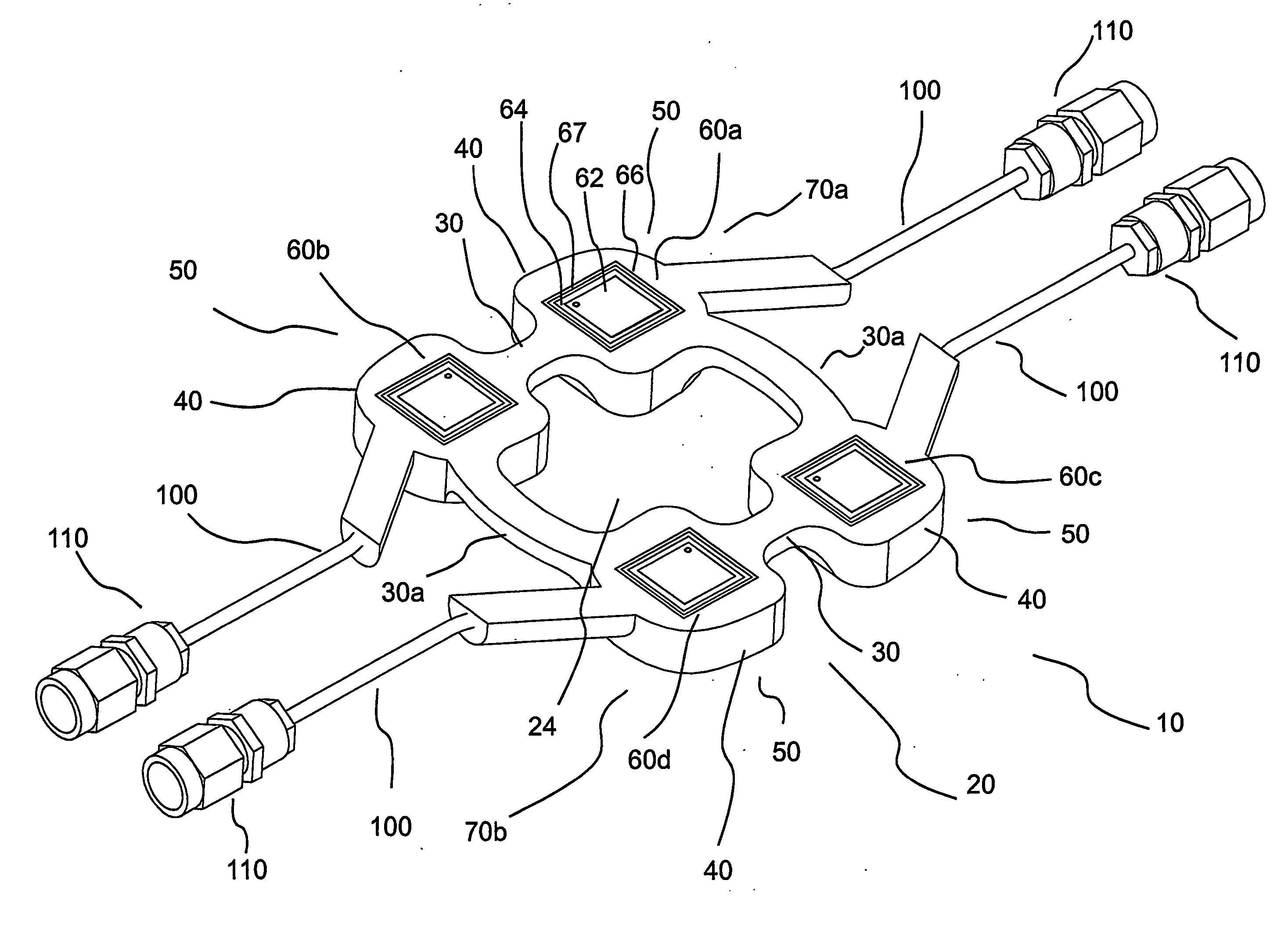
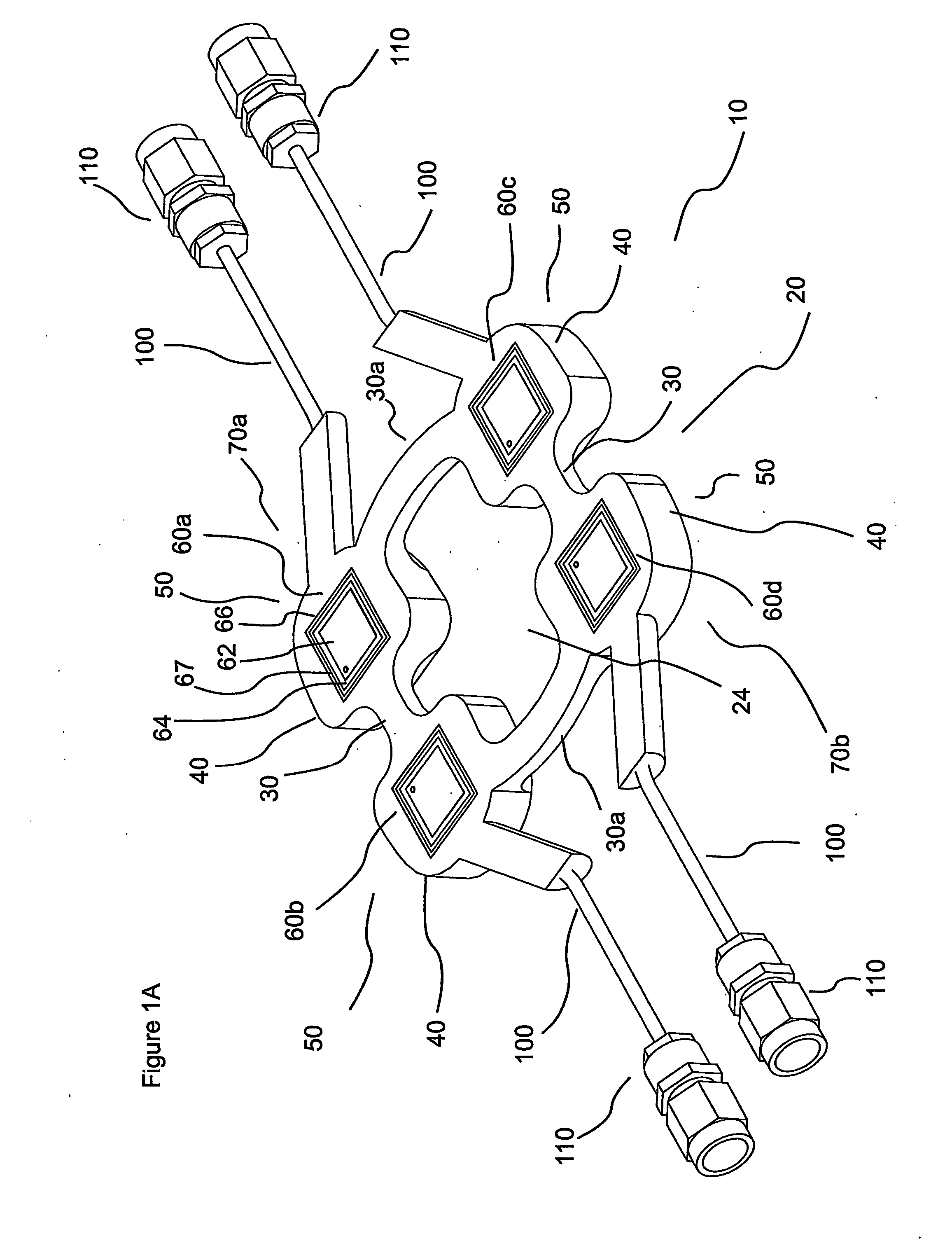
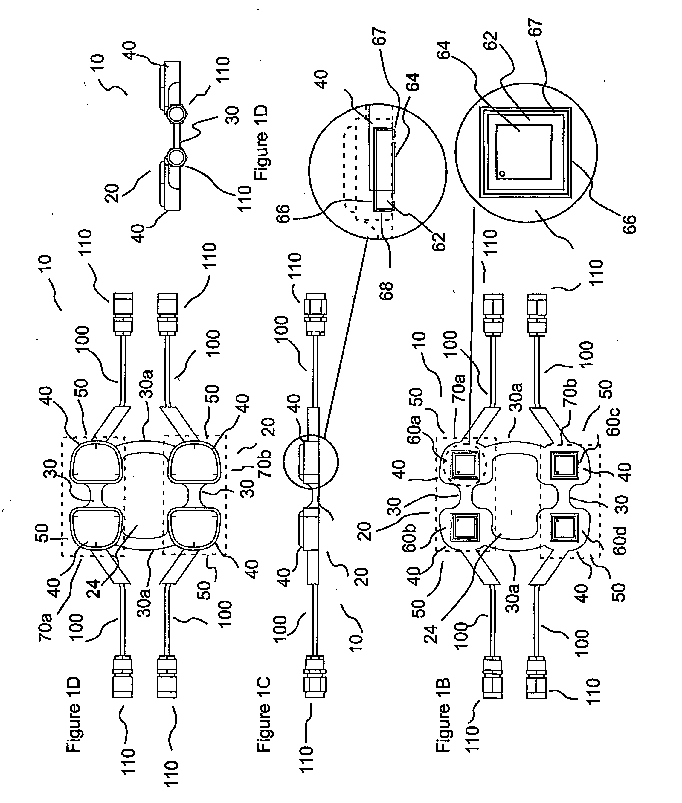
[0057] While the sensors, systems and methods of the present invention are generally applicable to the sensing any fluid within body tissue (whether a body fluid or an introduced fluid), the present invention is primarily described herein with reference to the representative example of extravasation of a fluid intended to be injected into a vascular structure. One skilled in the art will appreciate, however, that elevated, abnormal or changing levels of generally any fluid can be detected using the sensors, systems and methods of the present invention. Detection of body fluids in the present invention includes, but is not limited to, the detection of fluid changes as a result of edema, hematoma, ruptured bowel and colostomy tubing leakage into the peritoneal cavity. Introduced or foreign fluid detectible in the present invention include fluid introduced via generally any technique known in the medical arts including, but not limited to, injection, infusion and IV drip. As described ...


PUM


Abstract

A sensor device for detecting a change in the level of fluid within tissue of a body includes: a housing having a plurality of bridge segments, the bridge segments connecting at intersections and being arranged to circumscribe an opening defined by the housing; and a plurality of antenna elements at least partially seated within the housing at intersections of the bridge segments. Each of the plurality of antenna elements includes a generally planar antenna mounted to a substrate material at a base of the planar antenna. An outer surface of the planar antenna faces away from the substrate. Each of the plurality of antenna elements further includes an electrical shield surrounding the substrate. A sensor for detecting a change in the level of fluid within tissue of a body including a first antenna pair includes a first transmitting antenna and a first receiving antenna. The first transmitting antenna is spaced from and connected to the first receiving antenna by a first bridging segment. The sensor further includes at least a second antenna pair including a second transmitting antenna and a second receiving antenna. The second transmitting antenna is spaced from and connected to the second receiving antenna by a second bridging segment. The first antenna pair and the second antenna pair are placed in spaced connection by a first spacing segment and a second spacing segment so that an open area is defined by the first antenna pair, the second antenna pair, the first spacing segment and the second spacing segment.

Description

CROSS-REFERENCE TO RELATED APPLICATION [0001] This application claims benefit of U.S. Provisional Patent Application Ser. No. 60 / 514,355, filed Oct. 24, 2003, the disclosure of which is incorporated herein by reference.BACKGROUND OF THE INVENTION [0002] The present invention relates generally to the detection of fluid and / or other material in tissue, and especially, to systems, methods and / or devices for detecting changes in the level of fluid in tissue. In certain embodiments, the systems, methods and / or devices of the present invention detect if fluid level has increased or, has otherwise become abnormal. [0003] The following information is provided to assist the reader to understand the invention disclosed below and the environment in which it will typically be used. The terms used herein are not intended to be limited to any particular narrow interpretation unless clearly stated otherwise in this document. References set forth herein may facilitate understanding of the present i...

Claims


Application Information

Patent Timeline
IPC IPC(8): A61B5/05A61B5/053A61M5/168G01LG01N22/00
CPCA61B5/0004A61B5/0507A61B5/0537A61B5/411A61B5/4878A61B5/6833A61B2562/02A61B2562/046A61M5/16836A61M2205/3523
Inventor BOUTON, CHAD E.RUGGERI, FELICIA R.HARPHAM, R. READEHELD, JEFFREY R.
Owner BAYER HEALTHCARE LLC
Why Eureka
Try Eureka