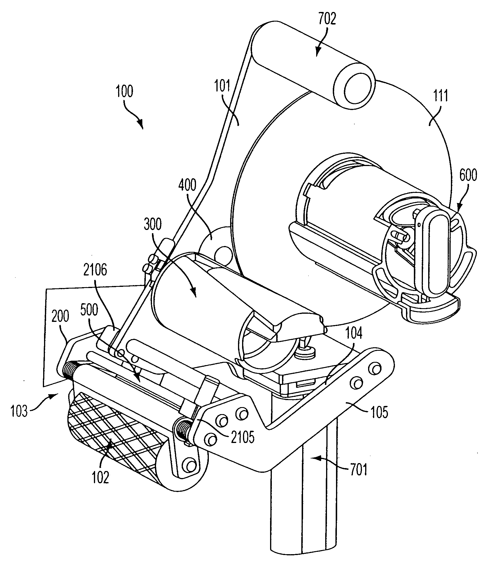
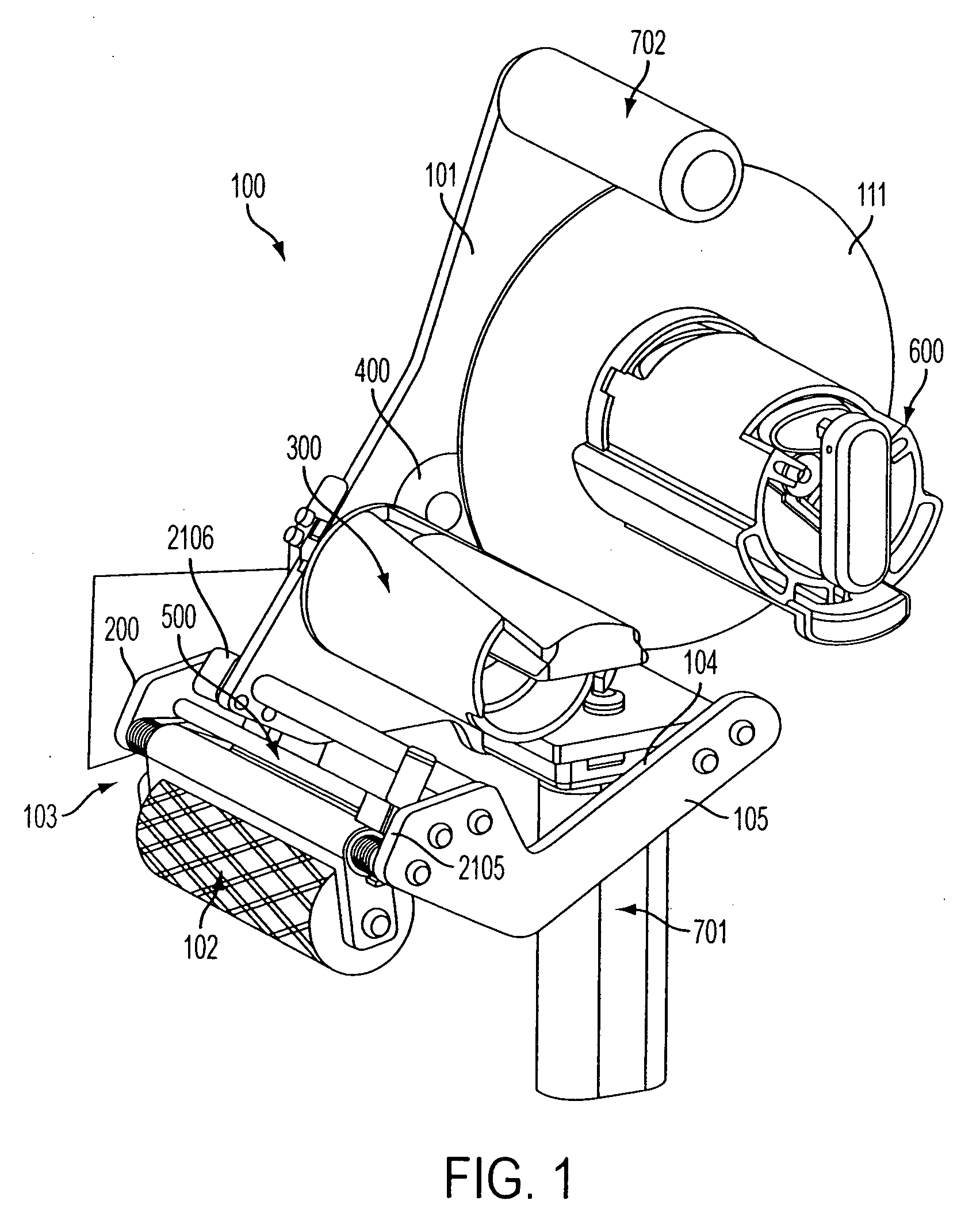
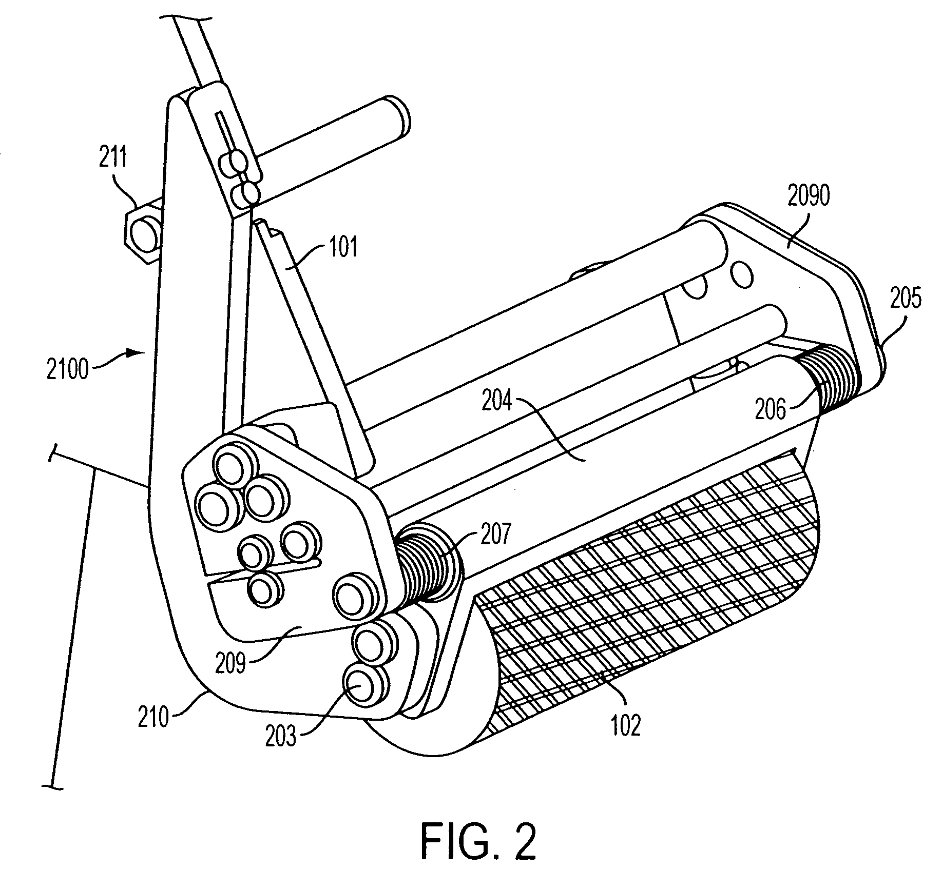
[0012] In one embodiment, a hand-held adhesive tape applicator device is provided for applying an adhesive tape material, comprising a frame extending in a longitudinal direction; an applicator roller
assembly including an applicator roller extending generally transverse to said longitudinal direction; a tape supply spool
assembly;
release liner take-up reel
assembly; a
gear train drivingly connecting the tape supply spool assembly and
release liner take-up reel assembly; a first hand grip mounted to a base portion of the frame; a stabilization brace, extending in a direction generally parallel to and laterally spaced from said longitudinal direction of the frame connecting (a) a first lateral side of the applicator roller assembly located opposite the second lateral side thereof located nearest the frame to (b) the base portion of the frame, effective to reduce bending of the applicator roller during tape application; and a
pressure feedback assembly including a reciprocally translatable interference component operable to interact with a gear associated with the drive means to generate
noise when pressure applied at the applicator roller is below a predetermined threshold pressure and to cease interaction with the gear and
noise generation when the threshold pressure is met or exceeded.
[0016] The stabilization brace prevents the pressure roller from bending relative to the transverse line of contact it makes on tape being fed to the pressure roller for application to an underlying surface, such that the entire width of the pressure roller can be maintained in constant contact with the tape at uniform pressure as the tape is applied, thereby reducing or preventing mistracking of the tape as it is being fed. The stabilization brace should be a rigid material construction. The shape of the stabilization brace is preferably swept downward along its main body between its opposite ends that are connected to applicator device so that access to the take-up reel assembly and other components of the applicator device are left unobstructed for access. During application of tape onto an inclined surface in particular using the tape applicator device, the tendency for uneven pressure to get applied across the width of the pressure roller may arise as the device is being manually manipulated by the user to accommodate the
topography of the work surface such that torque forces become exerted on the pressure roller. This can lead to the pressure roller being torqued as one lateral side of the pressure roller is pushed harder towards the tape and underlying surface while the opposite lateral side thereof tends to lift away from the tape and underlying surface being taped for a short time period. This transient bending phenomenon, if not prevented, tends to lead to mistracking of the tape as it is being fed. Mistracked tape may not come into contact with the pressure roller and thus that portion of the tape is not sealed properly to the surface being seamed or otherwise taped with the device. In an alternative embodiment, to stabilize the applicator device against bending of the pressure roller due to torque forces, a transverse stabilization bracket can be included in the applicator roll assembly which is mounted to extend transversely between the inner face of the frame and the opposite lateral side of the applicator roller assembly.
[0017] In another embodiment, the applicator device further includes a static dissipative polymeric sheet member encircling the supply tape reel assembly and located between the supply tape / fed tape and the frame, wherein the polymeric sheet member has a resistivity effective to prevent
discharge to / from
proximate human contact. This static dissipative member acts as a shield to keep tape adhesive and grit from getting into the gears of the tape applicator while also dissipating
static electricity that may build up due to the paper liner
rubbing against the
polymer shield member. In one embodiment, the polymeric sheet member comprises
acrylonitrile-butadiene-
styrene or other plastic surface-coated or filled throughout with an antistatic filler in amount effective to provide a resistivity of between about 106 to about 109 ohms per square. The antistatic filler may comprise non-carbon ally fillers used for this purpose or other suitable anti-static
filling materials. The plastic shield can be stamped or
cut from plastic sheeting containing a suitable static dissipative filler or
coating.
[0018] In yet another embodiment, the applicator device further comprises a torque tool comprising a plurality of rigid posts extending from a grippable piece that is stowable within a recess provided in the supply roll reel assembly. The take-up reel assembly further comprises a spring nut including a plurality of holes in a pattern adapted to receive the plurality of posts of the torque tool, wherein the torque tool is manually insertable via its posts into the spring nut holes and the torque tool is operable to adjust the rotational tension of the take-up reel assembly via
exertion of manual rotation force on the inserted torque tool. The torque tool can be used for adjusting the tension on the liner take-up reel assembly. For example, the liner tension provided by the take-up reel assembly tends to decrease over usage time, which can lead to sagging spent liner which may interfere with tape feeding. With the torque tool, the appropriate torque for the take-up reel can be set and checked as a
quality control step in the
assembly line and be readjusted easily over time by users in the field. The toque tool is tool carried aboard the applicator device that is readily available for use to tighten the tension on the take-up reel assembly in a facile and convenient manner.
[0019] In another embodiment, the applicator device further includes slip-resistant nubs integrally attached to and protruding from a side of the frame opposite the side upon which the take-up reel assembly and supply reel assembly are attached. The nubs have a closed end and an opposite open end, wherein the closed end comprises a generally flat surface from which a plurality of small integral projections extend to increase slip-resistance between the nubs and a contacted surface. The nubs may comprise composite structures including an elastomeric molding including the closed end, and the opposite open end holds a threaded nut, which allows the nubs to be removably fitted onto threaded bolt ends projecting through the frame. The nubs help to immobilize the applicator device in place if a user sets the device down on an inclined surface, such as a roof, as the nubs increase the slip-resistance of the device.
[0020] The adhesive tape applying devices embodied herein are operable to apply an adhesive tape material to a
substrate surface, such as an adhesive tape material comprising an adhesive layer carried on a
release liner, or alternatively a non-backed single-sided adhesive tape material. The hand grippable device is operable to dispense adhesive
layers supplied from a relatively large
diameter and heavy tape roll stored aboard the device onto uneven substrate surfaces. A roll of adhesive tape is mounted on and dispensed from the applicator device. The adhesive tape may be an adhesive tape material comprising an adhesive layer or film carried on at least one side of a releasable liner. The adhesive layer may be a single-side adhesive tape or double-sided adhesive tape. The device also may be used to apply non-lined single-sided adhesive tapes. The device is adapted to store,
handle and apply relatively hefty spools of adhesive tapes. These adhesive tapes include, for example, a roll of adhesive tape material wound on a core part thereof which is mounted on the supply spool assembly, wherein the tape adhesive material has a width of 2 to 8 inches and has a
diameter of 3 to 10 inches, and an initial roll weight of up to about 20 pounds, particularly from about 2 to about 10 pounds. The applicator device of embodiments herein can accommodate a relatively large
diameter roll of adhesive tape, which reduces the frequency of tape roll changes needed. In a particular embodiment, the adhesive tape material comprises an adhesive layer comprising a
moisture-resistant pressure-sensitive adhesive film carried on a face of a removable liner.

