
Hydraulic regenerative braking for a vehicle

a technology of hydraulic regenerative braking and vehicle, which is applied in the direction of braking system, cycle brake, cycle equipment, etc., can solve the problems of wasting valuable kinetic energy, requiring heavy duty batteries, and limiting the longetivity and feasibility of these vehicles, so as to minimize the frontal weight of the bicycle and improve the compactness of the bicycl

Active Publication Date: 2007-06-07
RGT UNIV OF MICHIGAN
View PDF11 Cites 28 Cited by
  • Summary
  • Abstract
  • Description
  • Claims
  • Application Information

AI Technical Summary

Benefits of technology

[0019] An advantage of the present invention is to provide a multi-stage or variable regenerative braking system for a vehicle, such as a bicycle, adaptable to store the energy for a 20 mph down to zero braking / deceleration and later release the energy for acceleration from 5-18 mph without pedal assistance (or 0-20 mph with minimal pedal assistance).
[0020] Another advantage of the present invention is to provide a regenerative braking system for a bicycle using a hydraulic mechanism disposed in and supported by the front wheel of the bicycle thereby improving compactness of the bicycle.
[0021] Still another advantage of the present invention is to provide to a rim designed to house two motors, a gear train, two accumulators or housings, two-way and / or three-way valves, and a hydraulic pumping system with all of these components being enclosed by side covers or wheel hubs formed from carbon-fiber to minimize the frontal weight of the bicycle.
[0022] Still another advantage of the present invention is to provide a regenerative braking system adaptable to provide variable braking for the bicycle in the form of two levels of braking torque accomplished by using two hydraulic motors.
[0023] Still another advantage of the present invention is to provide a two-wheel drive during acceleration while biking in the sand.

Problems solved by technology

First, these hybrid vehicles require heavy duty batteries to produce power.
These batteries are heavy and require frequent charging, which limits the longetivity and feasibility of these vehicles.
Thus, valuable kinetic energy is thrown away as lost heat during braking.
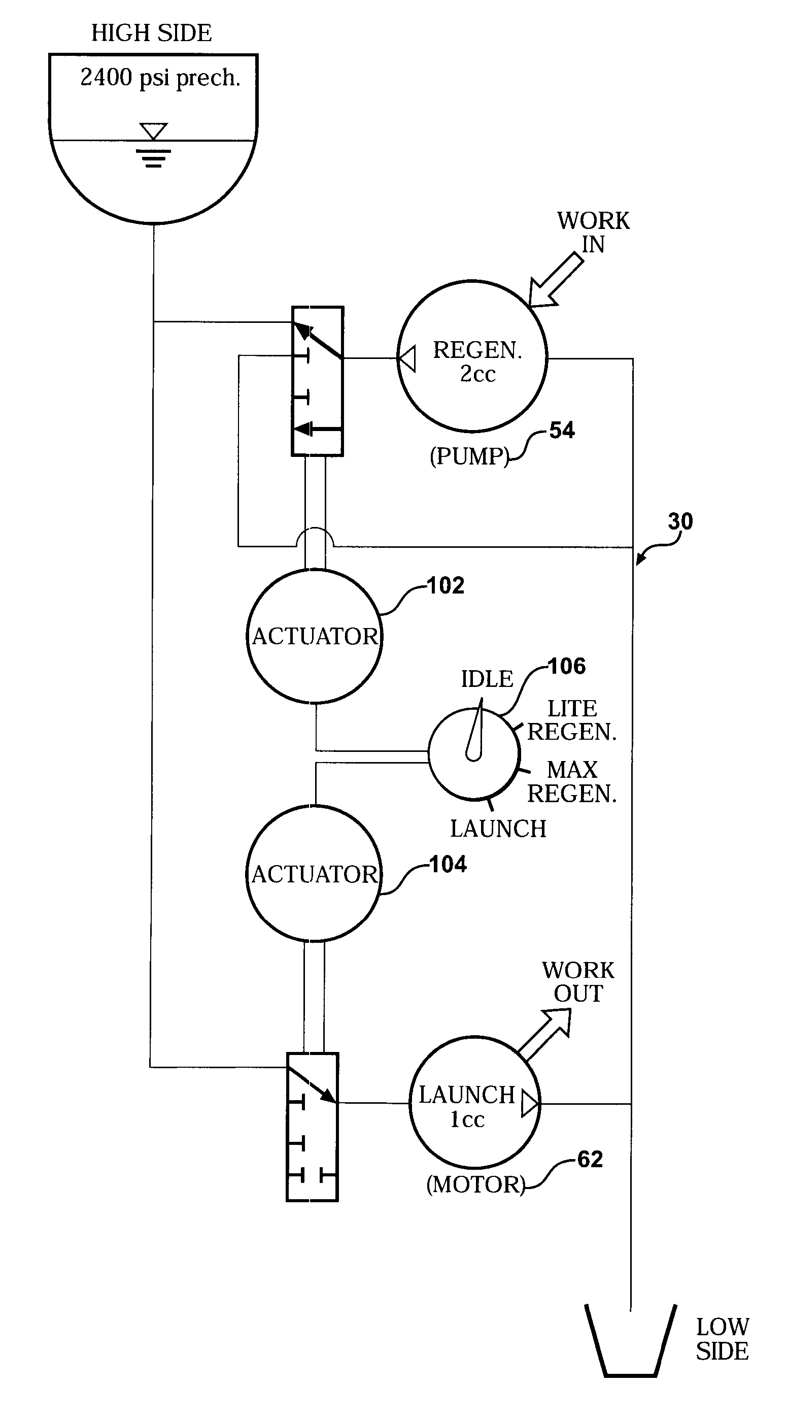
In addition, past bicycles have only utilized a single option for braking during the regeneration cycle.
The U.S. Pat. No. 4,087,105 to Amarantos's proposal is deficient in numerous respects.
Thus, the energy losses inherent in the pump and the motor will result in significant over-exertion.
Second, restricting the fluid flow out of the pump / motor may vary the braking, but will not vary the amount of energy regenerated.
Furthermore, this system requires a specially designed bicycle, and is not capable of retro-fit installation in an existing bicycle.
Also, a 0-20 mph acceleration for 220 pounds required nearly 5000 Joules of energy storage, and using the standard 4000 psi pumps, the fluid volume proposed in the U.S. Pat. No. 4,087,105 to Amarantos is severely underestimated.
This concept is deficient in that the hydraulic (or pneumatic) system does not directly generate the energy.
Not only do these additional components increase system complexity, weight and cost, but the numerous energy conversions introduce losses which are proportionally significant in a bicycle application.
Furthermore, this prior art design places propulsion units at both wheels, thereby further increasing the weight of the bicycle system.
The added weight of a 4 hp efficient electric motor would make it an unacceptable solution for a bicycle.
These devices provide an interesting way to transmit power to the wheels instead of using a chain, but provide no capability for energy storage.

Method used


Image

  • Hydraulic regenerative braking for a vehicle
  • Hydraulic regenerative braking for a vehicle
  • Hydraulic regenerative braking for a vehicle

Examples


Embodiment Construction

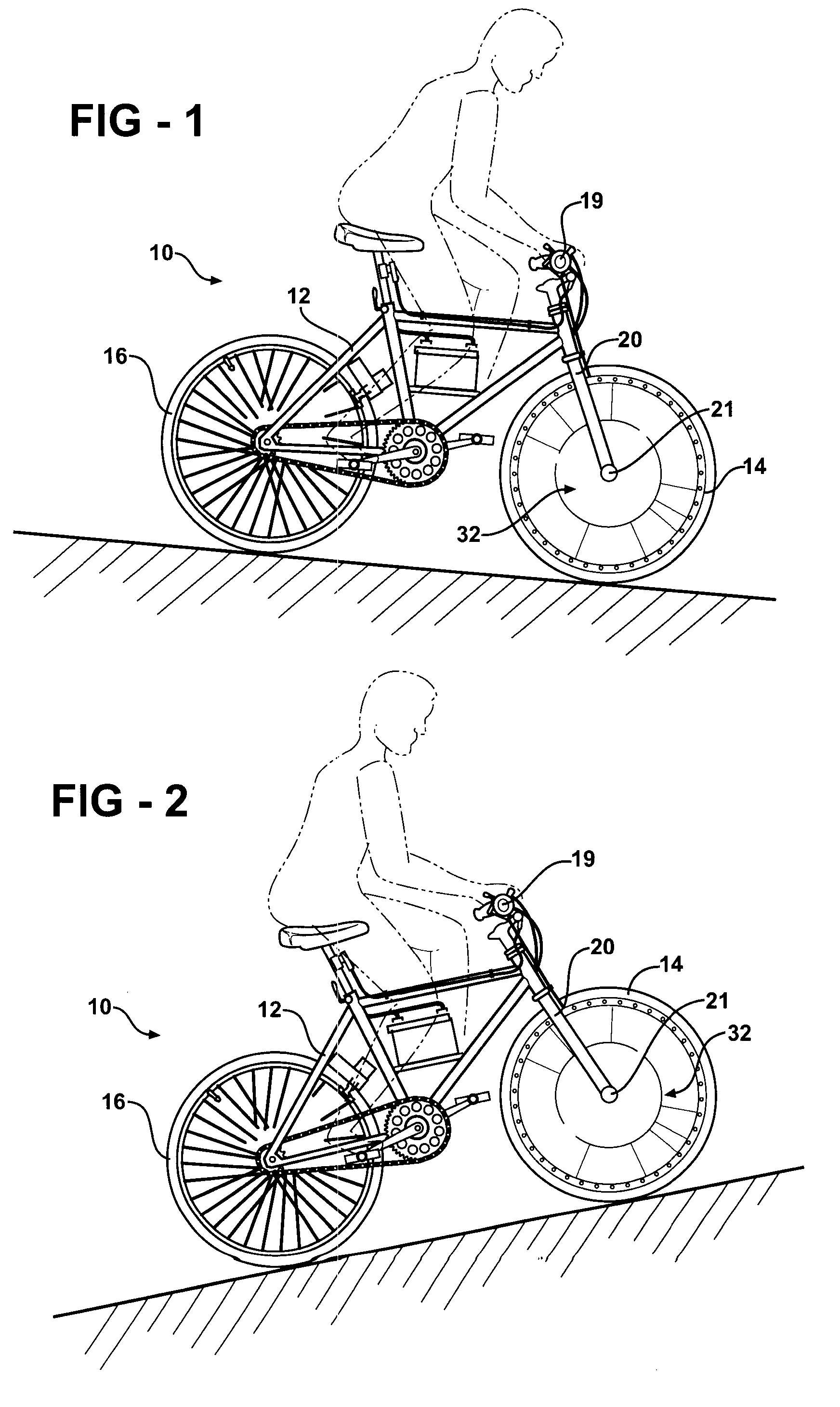
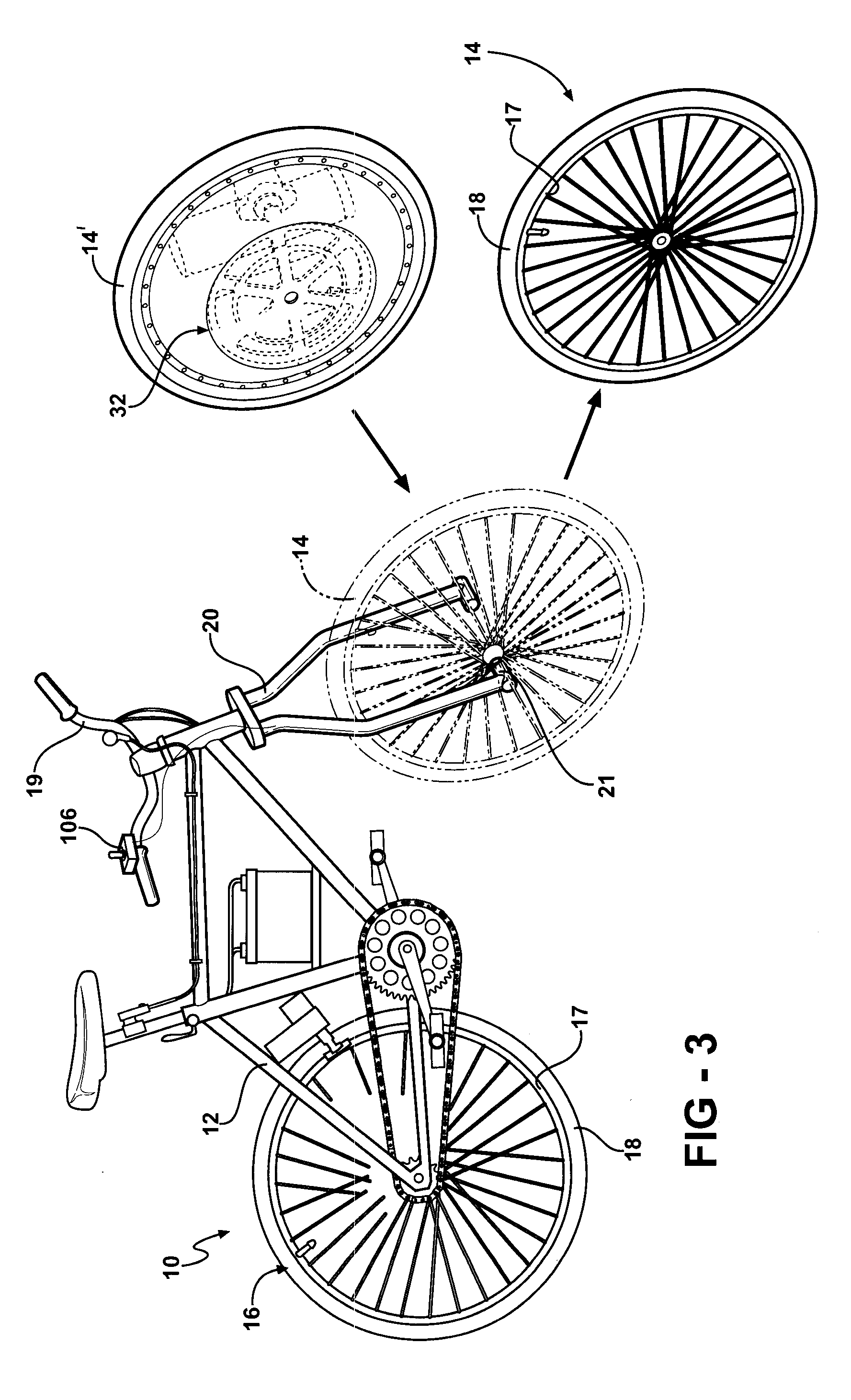
[0041] The present invention relates a regenerative braking device or system which allows a vehicle, such as, for example, a bicycle, to recapture part of the kinetic energy that would otherwise be lost when braking and make use of that energy released to assist take-off and hill climb maneuvers. The present invention is applicable to automobiles and other vehicles with the bicycle used for exemplary purposes without limiting the scope of the present invention.

[0042] Referring to the Figures, wherein like numerals indicate like or corresponding parts throughout the several views, a bicycle is generally shown at 10 in FIGS. 1 through 3. The bicycle 10 has a frame 12 rotatably supporting front 14 and rear 16 wheels, with each wheel 14 and 16 having a rim 17 and a tire 18. The front wheel 14 is steerable by way of a handlebar 19 joined to fork tubes 20 holding the axle 21 of the front wheel 14. FIG. 1 illustrates a rider on the bicycle 10 descending a slope, which is merely representa...


PUM


Abstract

A regenerative brake of the present invention presents a hydraulic device disposed in a front hub of a bicycle wheel. The device allows the bicycle to recapture part of the kinetic energy that would otherwise be lost when braking and make use of that power either by storing it for future use or feeding it back into a power system to be used. The hydraulic device may also be stored in a rear hub of the bicycle wheel.

Description

RELATED APPLICATION [0001] The application claims priority to U.S. Provisional Patent Application Ser. No. 60 / 748,078 filed Dec. 7, 2005, which is incorporated herein by reference in its entirety.A STATEMENT REGARDING FEDERALLY SPONSORED RESEARCH OR DEVELOPMENT [0002] This invention was made with government support under grant number XA-83194901-0 awarded by U.S. Environmental Protection Agency / ATD. The government has certain rights in the invention.FIELD OF THE INVENTION [0003] The present invention relates to a regenerative braking device or system which allows a vehicle, such as, for example, a bicycle, to recapture part of the kinetic energy that would otherwise be lost when braking and make use of the recaptured energy to assist take-off and hill climb maneuvers. BACKGROUND OF THE INVENTION [0004] Today, due to the lack in availability of petroleum oils, the trend towards Alternate Fueled Vehicles (AFV's), hybrid vehicles, and human powered vehicles (HPV's) has been the focus o...

Claims


Application Information

Patent Timeline
IPC IPC(8): B60T8/64
CPCB60K6/12B60T1/093B60T1/10B60T10/04B60W2300/36B62L1/00B62M1/10B62M6/25B62M7/12B62M19/00Y02T10/6208B60T8/267Y02T10/62
Inventor SWAIN, DAVID M.MOORE, JASON Z.MAURER, FRANK C.SHIH, ALBERT
Owner RGT UNIV OF MICHIGAN
Learn More