Fuel cell system

Inactive Publication Date: 2007-06-07
TOYOTA JIDOSHA KK
View PDF4 Cites 3 Cited by
  • Summary
  • Abstract
  • Description
  • Claims
  • Application Information

AI Technical Summary

Benefits of technology

[0004] An object of the present invention is to prevent degr

Problems solved by technology

However, when hydrogen permeable metal is exposed to hydrogen at low temperatures, the hydrogen permeable metal absorbs the hydrogen and it causes hydrogen embrittlement.
In a fuel cell with a hydrogen permeable metal layer,

Method used


Image

  • Fuel cell system
  • Fuel cell system
  • Fuel cell system

Examples


embodiment 2

B.

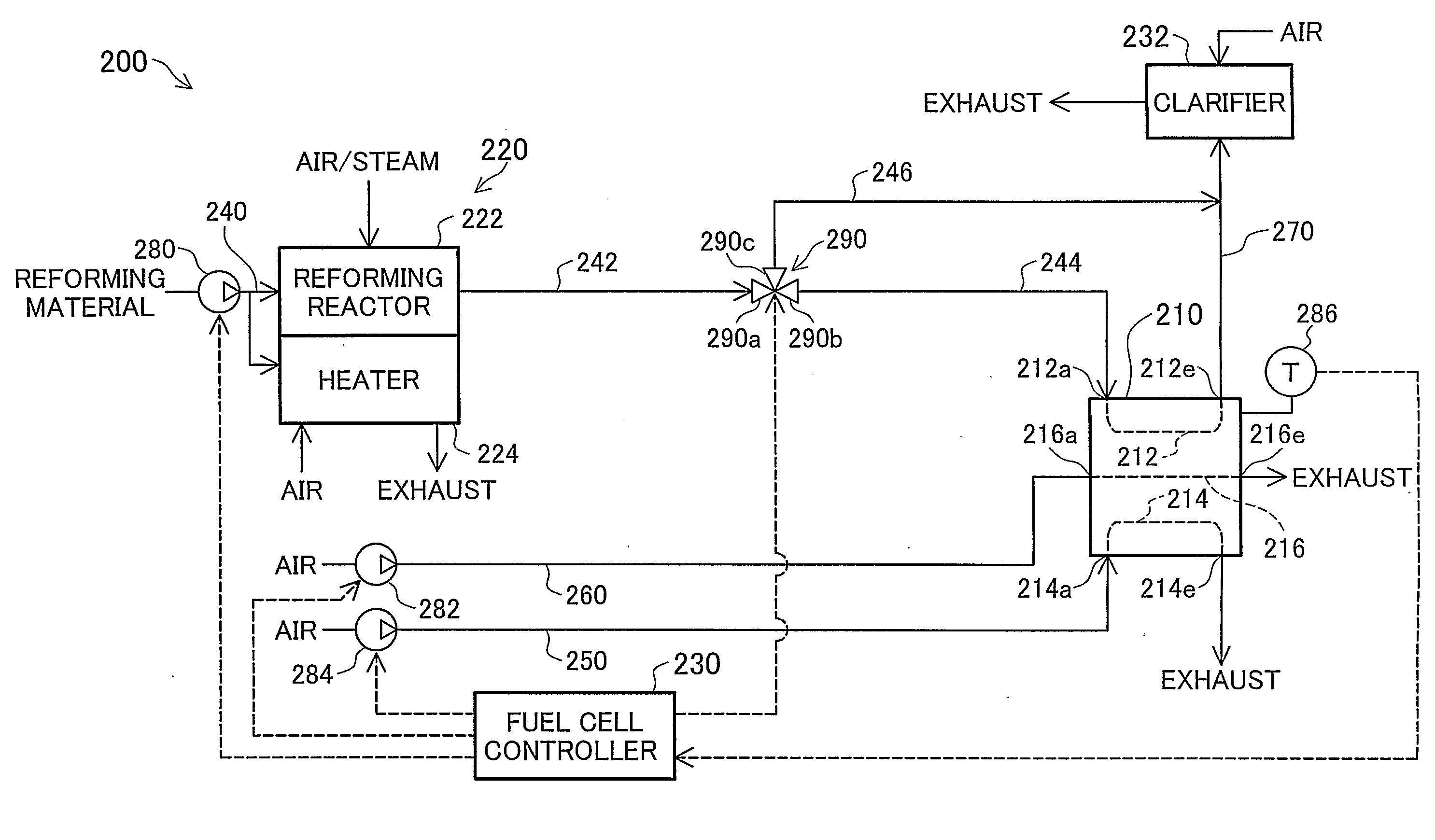
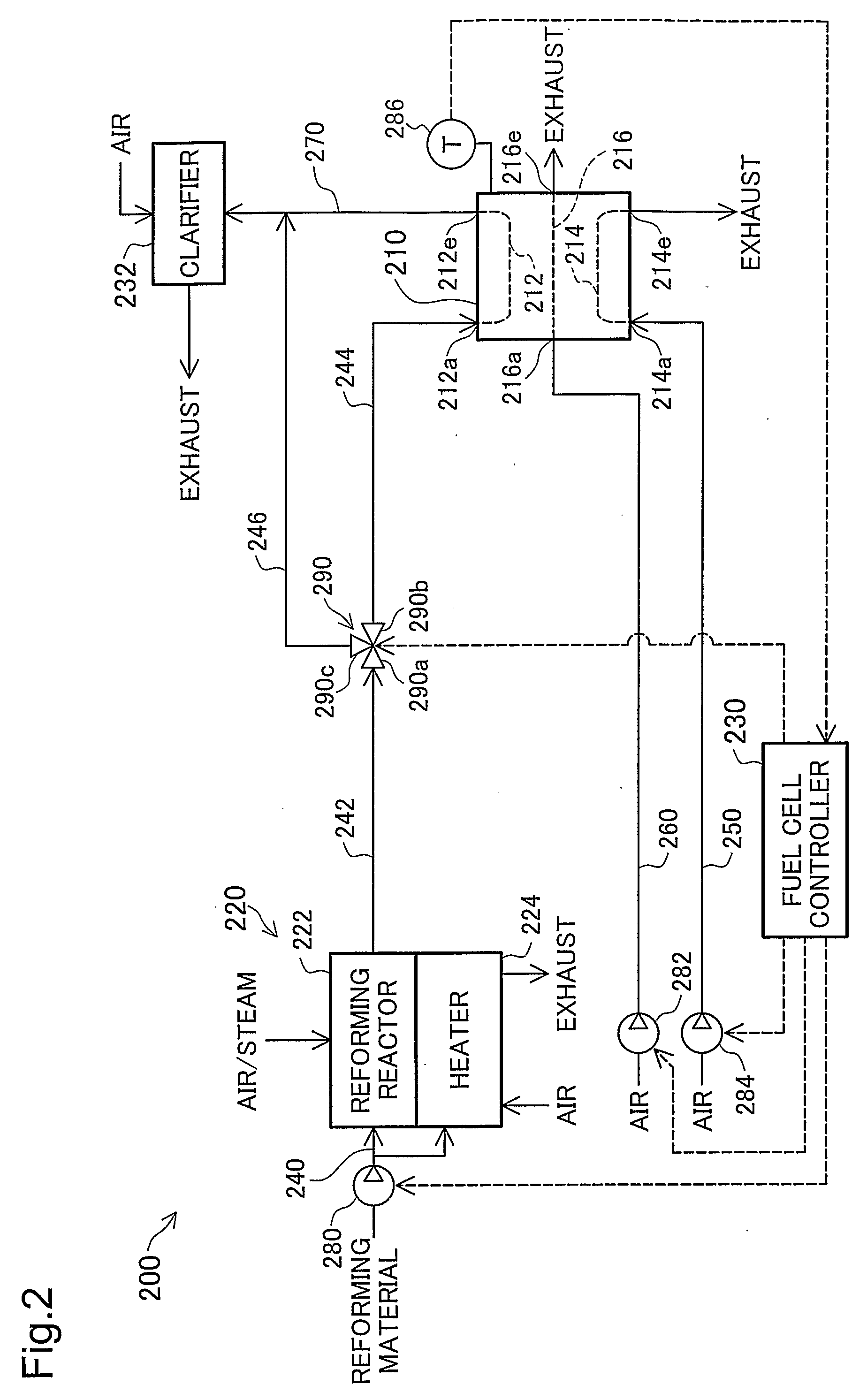
[0074]FIG. 5 is a schematic illustration showing the arrangement of a fuel cell system 200a in embodiment 2. The fuel cell system 200 (FIG. 2) differs from that in embodiment 1 by having a path for supplying diverted fuel gas to the cathode channel 214. In concrete terms, a third port 290c of the fuel gas bypass valve 290 provided at the fuel gas channel is connected to a first port 292a of the combustible gas supply valve 292 through a first fuel gas bypass piping 246a. A second port 292b of the combustible gas supply valve 292 is connected to a branch provided at the anode off gas piping 270 through the second fuel gas bypass piping 246b. An oxidizing gas piping 250a has a branch between the first air supply pump 284 and the first cathode channel end 214a. This branch is connected to the third port 292c of the combustible gas supply valve 292 through the combustible gas supply piping 246c. Other arrangements are virtually identical to those in embodiment 1.

[0075] A fuel cell co...

embodiment 3

C.

[0083]FIG. 7 is a schematic illustration showing the arrangement of the fuel cell system 200b in embodiment 3. The fuel cell system 200b differs from the fuel cell system 200a (FIG. 5) in embodiment 2 in that the diverted fuel gas is supplied to the heating part 224 of the reformer 220 instead of the clarifier 232. In concrete terms, the second port 292b of the combustible gas supply valve 292 is connected to the heating part 224 through the second combustible gas supply piping 246d. Other arrangements are virtually identical to those in embodiment 2.

[0084] In embodiment 3, when the operation mode of the fuel cell system 200b is bypassing mode, the diverted fuel gas is supplied to the heating part 224 through the second combustible gas supply piping 246d. Heat is generated in a combustive reaction between the supplied fuel gas and externally supplied air.

[0085] In this manner, when the operation mode is bypassing mode in embodiment 3, the fuel gas combusts at the heating part 22...

embodiment 4

D.

[0087]FIG. 8 is a schematic illustration showing the arrangement of the fuel cell system 200c in embodiment 4. The fuel cell system 200c differs from the fuel cell system 200 (FIG. 2) in embodiment 1 in that by having a heat exchanger 234 and a piping for supplying exhaust from the heating part 224 to the heat exchanger 234 to heat the cooling gas. In concrete terms, the second air supply pump 282 is connected to a first gas flow inlet 234a of the heat exchanger 234 through a first cooling gas piping 260a. The first gas flow inlet 234a is connected to a first gas flow outlet 234e through a channel inside the heat exchanger 234. The first gas flow outlet 234e is connected to a first coolant gas channel end 216a provided in the fuel cell 210 through a second cooling gas piping 260b. The second gas flow inlet 234b of the heat exchanger 234 is connected to a third port 294c of the reformer exhaust path switching valve 294 through a second reformer exhaust piping 247b. The first port 2...


PUM


Abstract

A technology for preventing degradation of a hydrogen permeable metal layer in a fuel cell 210 is provided. A fuel cell system 200 including a fuel cell 210 with an anode which has the hydrogen permeable metal layer comprises a fuel cell controller 230 for controlling the operation status of the fuel cell system 200, a temperature parameter acquisition section for acquiring a temperature parameter of the hydrogen permeable metal layer, and a hydrogen permeable metal layer degradation prevention section which reduces the hydrogen partial pressure in an anode channel 212 for supplying fuel gas to the anode. If a temperature of the hydrogen permeable metal layer represented by the temperature parameter deviates from a specified temperature range, the fuel cell controller 230 cause the hydrogen permeable metal layer degradation prevention section to operate for preventing degradation of the hydrogen permeable metal layer.

Description

TECHNICAL FIELD [0001] The present invention relates to a fuel cell system comprising fuel cell with a hydrogen permeable metal layer, and to a technique for preventing degradation of the hydrogen permeable metal layer in a fuel cell. BACKGROUND ART [0002] In a fuel cell system using reformed gas produced from a hydrocarbon reforming material as fuel, the reformed gas is purified to decrease the carbon monoxide (CO) in the reformed gas. The purification of reformed gas is carried out by a purifier such as a hydrogen purifier with a hydrogen permeable membrane and a selective oxidation part incorporated in the reformer. To avoid complication of the fuel cell system entailed by incorporation of such a purifier, JP05-299105 discloses a fuel cell with a hydrogen permeable metal layer on the electrolyte layer in which unpurified reformed gas can be used as fuel. [0003] However, when hydrogen permeable metal is exposed to hydrogen at low temperatures, the hydrogen permeable metal absorbs ...

Claims


Application Information

Patent Timeline
IPC IPC(8): H01M8/04H01M8/02H01M4/90H01M4/92H01M4/94H01M8/06H01M8/12
CPCH01M4/92H01M4/94H01M8/04007H01M8/04089H01M8/0612H01M8/0662H01M8/1213Y02E60/521Y02E60/525Y02E60/50
Inventor OGINO, SHIGERUAOYAMA, SATOSHIIZAWA, YASUHIROSHIOKAWA, SATOSHISHIMAZU, TAKASHIAOKI, HIROSHIMITSUI, HIROYUKI
Owner TOYOTA JIDOSHA KK
Why Eureka
Try Eureka