Pattern formed body and method for manufacturing same

a pattern and body technology, applied in the field of pattern formed bodies, can solve the problems of deterioration of materials, difficulty in locating printing, and other problems, and achieve the effect of high precision of the functional part, good optical transparency of the pattern formed body itself, and low haze valu

Inactive Publication Date: 2007-06-07
DAI NIPPON PRINTING CO LTD
View PDF7 Cites 10 Cited by
  • Summary
  • Abstract
  • Description
  • Claims
  • Application Information

AI Technical Summary

Benefits of technology

[0031] The invention has an advantage that when a functional part, such as a color layer, is formed in the opening part in the pattern formed body to manufacture a functional element such as a color filter, it is possible to prevent the fluorine atom in the photocatalyst containing layer from eluting out in subsequent steps so as to produce a bad effect onto the functional part since no fluorine atom is contained in the photocatalyst containing layer.
[0032] In the invention, the film thickness of the photocatalyst containing layer ranges preferably from 10 to 200 nm. This...

Problems solved by technology

Accordingly, there are caused such problems that waste liquid generated needs to be disposed.
Additionally, there also arises a problem that when a functional material is used as the photoresist, the material is deteriorated by the alkaline solution or the like that is used for the development.
However, the pattern formed by printing has problems about location accuracy and others.
Thus, a highly precise pattern is not easily formed.
According to this method, however, w...

Method used


Image

  • Pattern formed body and method for manufacturing same
  • Pattern formed body and method for manufacturing same
  • Pattern formed body and method for manufacturing same

Examples


third embodiment

(3) Third Embodiment

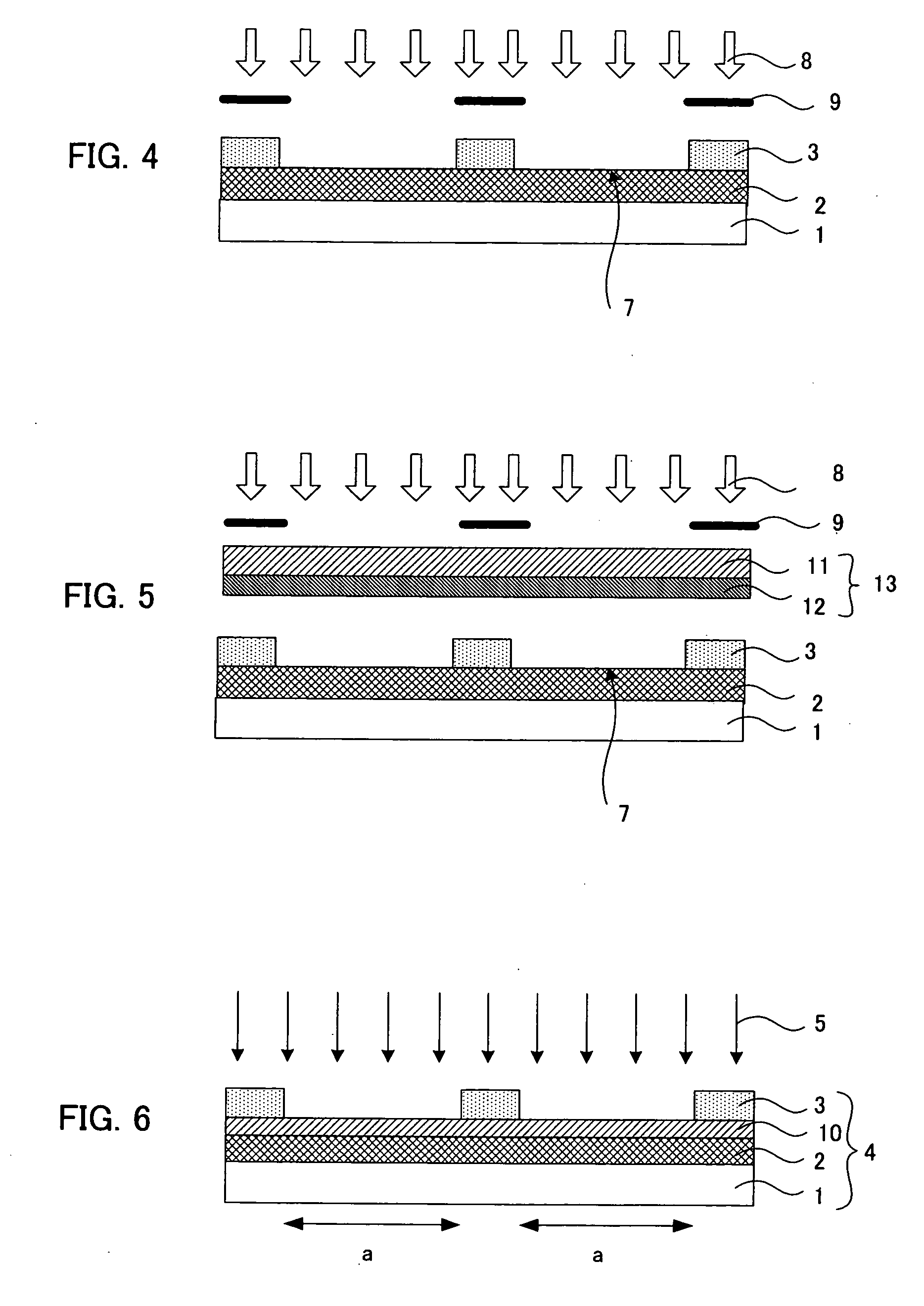
[0252] Next, the third embodiment of the method for the energy radiating in the liquid repellent material removing step is described. As illustrated in, for example, FIG. 9, the third embodiment of the method for the energy radiating in the present step is an embodiment of radiating energy 8 to the opening part 7 partitioned by the light shielding part 6 from the side of the light shielding part 6 of the base material 1, on which the light shielding part 6 is formed, using, for example, a photomask 9, thereby removing liquid repellent materials present on the surfaces of the opening part 7.

[0253] According to the embodiment, the energy is radiated to the opening part partitioned by the light shielding part from the side of the light shielding part, whereby the liquid repellent materials present on the opening part surface can be removed by the action of the photocatalyst accompanying the energy radiation. The embodiment has an advantage that the liquid repellent...

fourth embodiment

(4) Fourth Embodiment

[0255] Next, the fourth embodiment of the method for the energy radiating in the liquid repellent material removing step is described. As illustrated in, for example, FIG. 10, the fourth embodiment of the method for the energy radiating in the step is an embodiment of preparing a photocatalyst processing layer side substrate 13 having a base body 11, and a photocatalyst processing layer 12 formed on the base body 11 and containing at least a photocatalyst, arranging the photocatalyst processing layer 12 and the light shielding part 6 oppositely to each other, and radiating energy 8 thereto from the side of the photocatalyst processing layer side substrate 13, using, for example, a photomask 9, thereby removing liquid repellent materials present on the surface of the opening part 7 partitioned by the light shielding part 6.

[0256] According to the embodiment, the liquid repellent materials on the opening part surface can be removed not only by the action of the p...

first embodiment

(1) First Embodiment

[0262] First, the first embodiment of the pattern formed body of the aspect is described. The pattern formed body is a body having a base material, a photocatalyst containing layer formed on the base material and containing at least a photocatalyst, and a liquid repellent resin layer formed in a pattern form on the photocatalyst containing layer and containing, in its surface, a fluorine atom wherein a region of the photocatalyst containing layer where the liquid repellent resin layer is not formed is rendered a lyophilic region which contains, in its surface, no fluorine atom.

[0263] As illustrated in FIG. 11, an example of the pattern formed body of the present embodiment is an example wherein a photocatalyst containing layer 2 is formed on a base material 1 and further a liquid repellent resin layer 20 is formed thereon in a pattern form. In the embodiment, the surface of the liquid repellent resin layer 20 contains a fluorine atom, and the surface of region w...


PUM


Abstract

A main object of the present invention is to provide a high quality pattern formed body, wherein only the target region is made liquid repellent with a high precision at the time of forming a pattern made of a lyophilic region and a liquid repellent region by use of plasma radiating; and a method for manufacturing the same. To achieve the object, the present invention provides a method for manufacturing a pattern formed body comprising a plasma radiating step of radiating plasma to a patterning substrate having: a base material; a photocatalyst containing layer formed on the base material and containing at least a photocatalyst; and a resin layer formed in a pattern form on the photocatalyst containing layer and containing at least a resin, wherein a fluorine compound is used as an introduction gas to radiate the plasma to make the upper face of the resin layer liquid repellent.

Description

BACKGROUND OF THE INVENTION [0001] 1. Field of the Invention [0002] The present invention relates to a pattern formed body wherein a region having liquid repellency and a region having lyophilicity are formed with a high precision, and a method for manufacturing the same. [0003] 2. Description of the Related Art [0004] Conventionally, various methods have been suggested as a method for manufacturing a pattern formed body wherein various patterns such as designs, images, characters, and circuits are formed on a base material. [0005] As a method to form a pattern highly precisely, the following is known: a method for manufacturing a pattern formed body by photolithography of radiating light in a pattern form to a photoresist layer applied on a base material and developing the photoresist after the radiation to perform etching, or of using a material having functionality as a photoresist and radiating light to the photoresist so as to form a target pattern directly. [0006] The formatio...

Claims


Application Information

Patent Timeline
IPC IPC(8): H01L21/00
CPCG02F1/133516
Inventor KOBAYASHI, HIRONORIMATSUKAWA, AYAO
Owner DAI NIPPON PRINTING CO LTD
Why Eureka
Try Eureka