Imaging apparatus and image processor

Inactive Publication Date: 2007-06-14
SONY CORP
View PDF7 Cites 76 Cited by
  • Summary
  • Abstract
  • Description
  • Claims
  • Application Information

AI Technical Summary

Benefits of technology

[0025] According to the imaging apparatus according to an embodiment of the present invention, if a subject is bright and an image with an adequate S/N ratio is imaged, an image in which the color reproducibility has been significantly improved is output, and if a subject is dark and an image

Problems solved by technology

The linear matrix operation processing for improvement of color reproducibility causes a side effect in which noise is increased.
In particular, since the signal level of an image is low under low illumination, image quality degradation due to a decrease in the S/N ratio is conspicuous.
As will be described later, however, if matrix coefficients are changed under low illumination in a system shown in FIG. 9, the white balance of an output ima

Method used


Image

  • Imaging apparatus and image processor
  • Imaging apparatus and image processor
  • Imaging apparatus and image processor

Examples


Example

FIRST EMBODIMENT

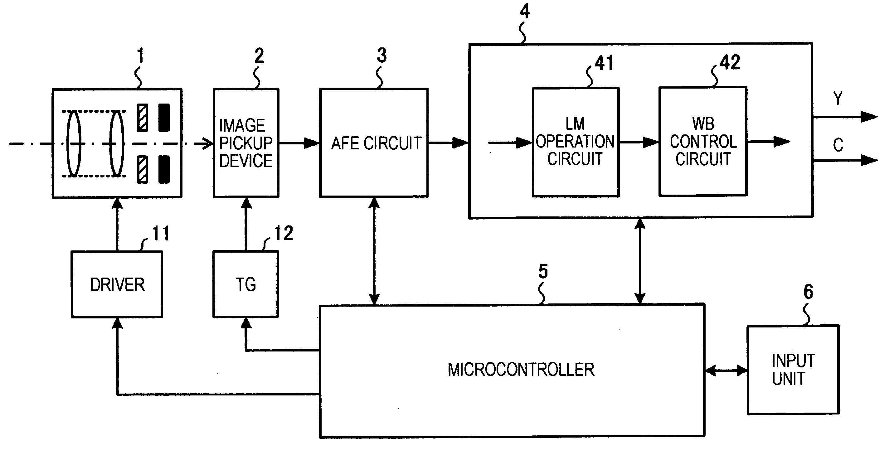
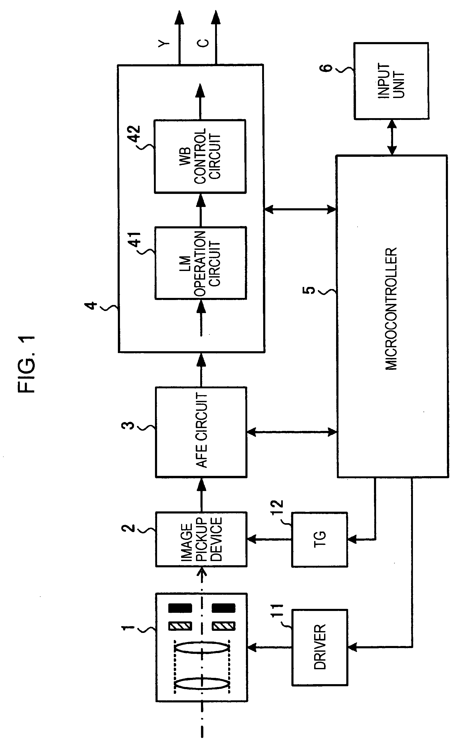
[0038]FIG. 1 is a block diagram showing the configuration of an imaging apparatus according to the first embodiment of the present invention.

[0039] The imaging apparatus shown in FIG. 1 is provided with an optical block 1, an image pickup device 2, an AFE (Analog Front End) circuit 3, a camera signal processing circuit 4, a microcontroller 5, an input unit 6, a driver 11 for driving various mechanisms included in the optical block 1, and a timing generator (TG) 12 for driving the image pickup device 2.

[0040] The optical block 1 is provided with a lens for focusing light from a subject onto the image pickup device 2, a driving mechanism for moving the lens to cause the lens to perform focusing and zooming operations, a mechanical shutter, and a diaphragm. The driver 11 performs drive control upon each mechanism included in the optical block 1 in accordance with a control signal transmitted from the microcontroller 5.

[0041] The image pickup device 2 is a CCD (Charg...

Example

SECOND EMBODIMENT

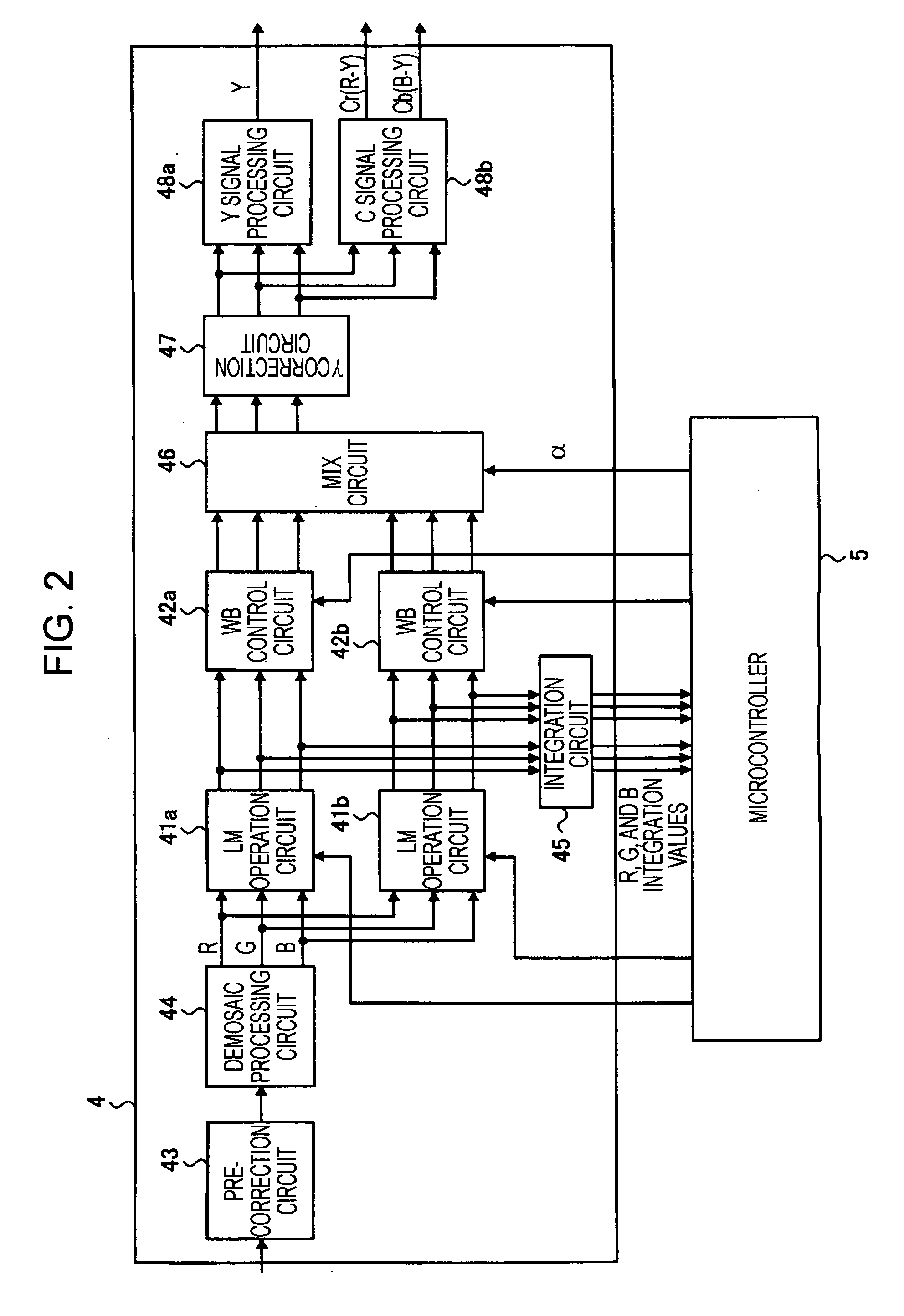
[0075]FIG. 6 is a block diagram showing the internal configuration of a camera signal processing circuit according to the second embodiment of the present invention. In FIG. 6, the same reference numerals are used for functions similar to those shown in FIG. 2 to avoid repeated description.

[0076] Like the camera signal processing circuit according to the first embodiment shown in FIG. 2, a camera signal processing circuit 4a has a basic configuration that includes two signal processing systems for performing linear matrix operations and white balance control and the MIX circuit 46 for combining image signals output from the signal processing systems. The difference between the first and second embodiments is that the function of calculating the combination ratio α to be set for the MIX circuit 46 is achieved by a Y signal generation circuit 49 and an α calculation circuit 50 instead of the microcontroller 5.

[0077] The Y signal generation circuit 49 generates a Y ...

Example

THIRD EMBODIMENT

[0081]FIG. 8 is a block diagram showing the internal configuration of a camera signal processing circuit according to the third embodiment of the present invention. In FIG. 8, the same reference numerals are used for functions similar to those shown in FIG. 2 to avoid repeated description.

[0082] The feature of a camera signal processing circuit 4b according to the third embodiment is that it has both a calculation function based on an illumination level which has been described in the first embodiment and a calculation function based on a brightness level on a pixel-by-pixel basis which has been described in the second embodiment as a function of calculating the combination ratio α for the MIX circuit 46, and selectively sets one of the calculated values for the MIX circuit 46.

[0083] Referring to FIG. 8, the microcontroller 5 obtains an illumination level on the basis of the limited amount of exposure set for an exposure control mechanism and a brightness level ba...


PUM


Abstract

An imaging apparatus for imaging an image using a solid-state image pickup device includes a first linear matrix operation unit configured to perform matrix conversion upon a color component of an image signal obtained by imaging using coefficients capable of improving color reproducibility; a second linear matrix operation unit configured to perform matrix conversion upon the color component using coefficients capable of achieving noise component reduction; a signal combining unit configured to combine image signals output from a plurality of signal processing systems each of which includes one of the first or second linear matrix operation units; and a combination ratio setting unit configured to set a combination ratio so that, when a subject is bright, an image signal output from the signal processing system that includes the first linear matrix operation unit can be combined in an amount larger than the image signals output from the other signal processing systems.

Description

CROSS-REFERENCE TO RELATED APPLICATIONS [0001] The present application claims priority from Japanese Patent Application No. JP 2005-281380 filed on Sep. 28, 2005, the disclosure of which is hereby incorporated by reference herein. BACKGROUND OF THE INVENTION [0002] 1. Field of the Invention [0003] The present invention relates to imaging apparatuses for picking up images using solid-state image pickup devices and image processors for performing color correction processing upon input image signals, and, more particularly, to an imaging apparatus having a linear matrix operation function and an image processor. [0004] 2. Description of the Related Art [0005] A linear matrix operation technique is attracting attention as a technique for correctly reproducing colors in imaging apparatuses that use solid-state image pickup devices, such as a digital still camera and a digital video camera. The linear matrix operation technique improves color reproducibility by performing a linear matrix ...

Claims


Application Information

Patent Timeline
IPC IPC(8): H04N5/228H04N9/04H04N9/67H04N9/73
CPCH04N1/58H04N1/6027H04N25/60H04N23/12
Inventor CHIBA, TAKUYAYONEDA, YUTAKAMATSUI, AKIRAKINOSHITA, MASAYA
Owner SONY CORP
Why Eureka
Try Eureka