Thermal isolation between heating and sensing for flow sensors

a flow sensor and thermal isolation technology, applied in the field of sensing devices and methods, can solve the problems of reducing thermal efficiency and therefore signal quality, discharging power away, and natural gas composition change, so as to reduce output distortion, response time, warm-up time, drift and nois

Active Publication Date: 2007-06-21
HONEYWELL INT INC
View PDF20 Cites 13 Cited by
  • Summary
  • Abstract
  • Description
  • Claims
  • Application Information

AI Technical Summary

Benefits of technology

[0014] The aforementioned aspects and other objectives and advantages can now be achieved as described herein. A flow sensor system is disclosed, which includes a plurality of flow sensor chips, wherein each flow sensor chip among the plurality of flow sensor chips comprises a substrate, a heater element, a heater control circuit, and flow sensor component formed on the substrate, wherein the heater element is disposed separately from the heater control circuit on the substrate, wherein the heater control circuit is thermally isolated from the heater element and the flow sensor component. Additionally, an air gap can be formed between each sensor chip among the plurality of flow sensor chips, wherein the plurality of flow sensor chips comprises a flow sensor system in which each of the flow sensor chips are separated from one another by the air gap formed therebetween in order to reduce output distortion, response time, warm-up time, drift and noise associated with the plurality of flow sensor chips.

Problems solved by technology

For example, in a semiconductor processing system that passes a nitrogen-based gas, the nitrogen-based gas may at times be replaced by a hydrogen-based or helium-based gas, depending on the needs of the process; or in a natural gas metering system, the composition of the natural gas may change due to non-uniform concentration profiles of the gas.
Such material, however, typically dissipates power away from the fluid and the sensor, thereby reducing the thermal efficiency and therefore the signal quality.
The use of such a thin bridge, however, is inherently fragile and if exposed to liquid flow results in damage to the bridge, in effect a “wash out,” which effectively destroys the sensing capability of the airflow sensing chip.
In such a situation, however, a different substrate is required because standard silicon has a very high thermal conductivity and the resistors associated with the sensor chip tend to operate toward the same temperature, which prevents proper sensing functions.
Nickel-iron may also be utilized, but tends to corrode easily.
Processing Pt on Pyrex generally does not work well, because the Pyrex melts at the Pt anneal temperature.
Constructing a liquid flow sensor on solid quartz is possible, but its production has been limited.
Compared to other airflow sensors, however, the resulting product has low sensitivity, far higher drift, very large temperature errors, excessive power dissipation, and a very long warm-up time.
Most of these problems are due to the thermal cross talk (inside the quartz) between those resistors which, on an airflow sensor, are thermally isolated (by air gaps).
It is often necessary, however, to minimize heat that flows in other directions, which lowers thermal efficiency, distorts output signals, increases response time and warm-up time, causes output drift / noise and requires excessive power to operate.

Method used


Image

  • Thermal isolation between heating and sensing for flow sensors
  • Thermal isolation between heating and sensing for flow sensors

Examples


Embodiment Construction

[0019] The particular values and configurations discussed in these non-limiting examples can be varied and are cited merely to illustrate at least one embodiment and are not intended to limit the scope thereof.

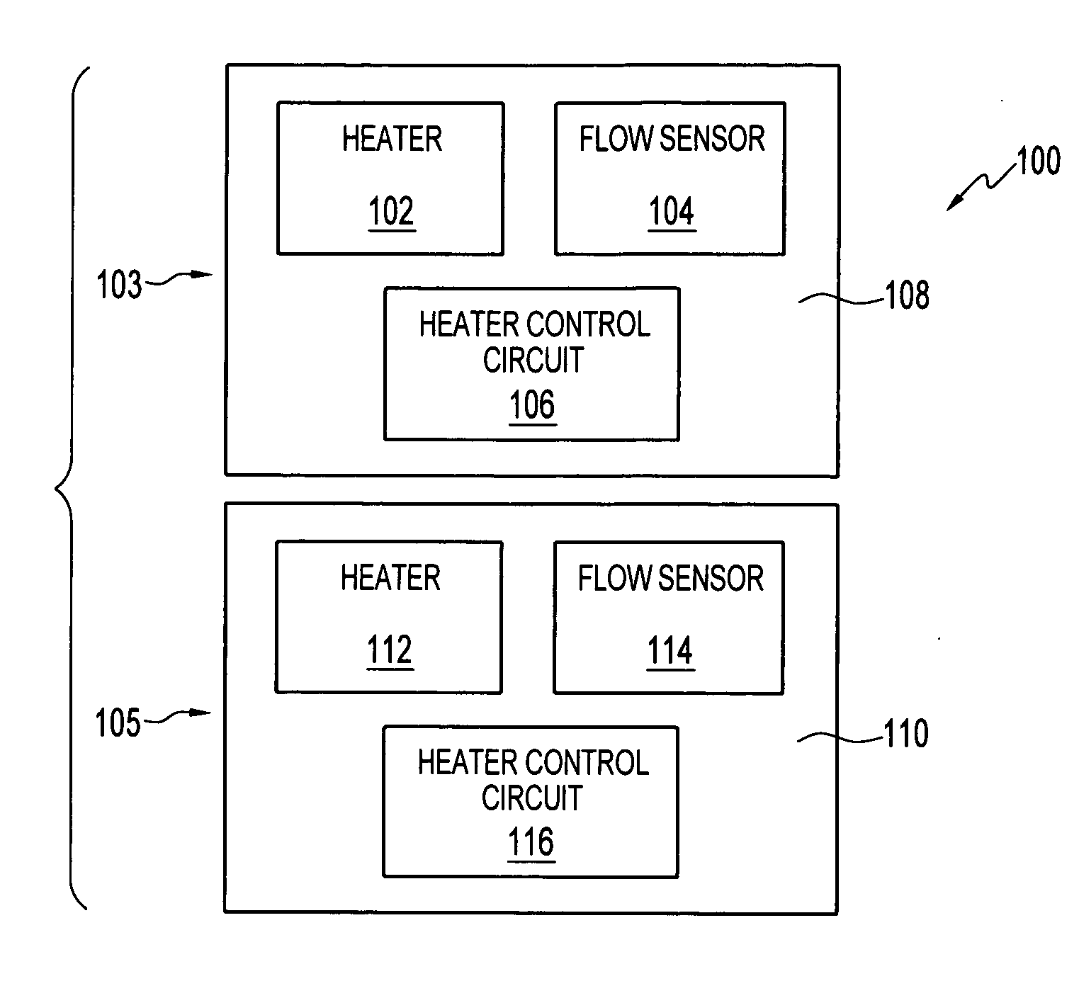
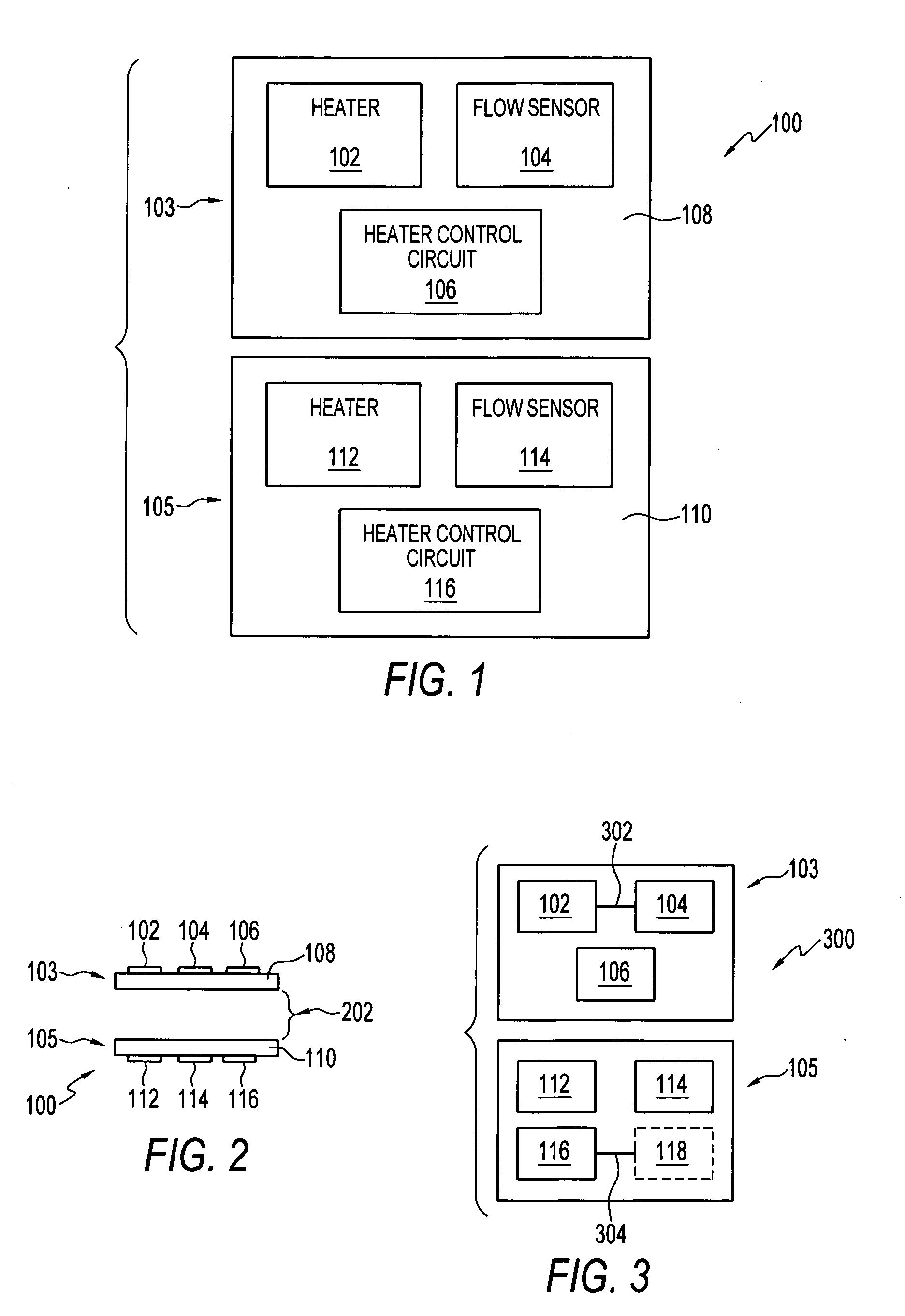
[0020]FIG. 1 illustrates a flow sensor system 100 comprising a plurality of sensor chips 103, 105, in accordance with a preferred embodiment. FIG. 2 illustrates a side view of the flow sensor system 100 depicted in FIG. 1 in accordance with a preferred embodiment. The flow sensor system 100 generally includes a plurality of flow sensor chips 103, 105, wherein each flow sensor chip 103, 105 respectively comprises a substrate 108, 110, a heater element 102, 112, a heater control circuit 106, 116, and a flow sensor component 104, 114 formed on the substrates 108, 110, wherein the heater elements 102, 112 are disposed separately from the heater control circuits 106, 116 on the substrates 108, 110. Each heater control circuit 106, 116 can be respectively thermally isolated from th...


PUM


Abstract

A flow sensor system includes a plurality of flow sensor chips, wherein each flow sensor chip among the plurality of flow sensor chips comprises a substrate, a heater element, a heater control circuit, and flow sensor component formed on the substrate, wherein the heater element is disposed separately from the heater control circuit on the substrate, wherein the heater control circuit is thermally isolated from the heater element and the flow sensor component. Additionally, an air gap can be formed between each sensor chip among the plurality of flow sensor chips, wherein the plurality of flow sensor chips comprises a flow sensor system in which each of the flow sensor chips are separated from one another by the air gap formed therebetween in order to reduce output distortion, response time, warm-up time, drift and noise associated with the plurality of flow sensor chips.

Description

TECHNICAL FIELD [0001] Embodiments are generally related to sensing devices and methods. Embodiments are also related to flow sensors and ambient temperature sensors. Embodiments are also related to systems and methods for configuring flow sensor integrated circuit (IC) chips. BACKGROUND OF THE INVENTION [0002] Sensors have been used to measure flow rates in various medical, process, and industrial applications, ranging from portable ventilators supplying anesthetizing agents to large-scale processing plants in a chemical plant. In these applications, flow control is an inherent aspect of proper operation, which is achieved in part by using flow sensors to measure the flow rate of a fluid within the flow system. In many flow systems, e.g., fuel cell flow systems containing a binary mixture of methanol and water, the chemical composition of the fluid may change frequently. [0003] A flow system is often required to flow more than one fluid having different chemical and thermo physical...

Claims


Application Information

Patent Timeline
Patent Type & Authority Applications(United States)
IPC IPC(8): G01F1/68
CPCG01F1/684G01F1/6845
Inventor GEHMAN, RICHARD W.MARCHINI, MICHAEL G.MURRAY, MARTIN G.
Owner HONEYWELL INT INC
Why Eureka
Try Eureka