

Method for the removal of deposits on the internal walls of industrial furnaces of bunkers
- Summary
- Abstract
- Description
- Claims
- Application Information
AI Technical Summary
Benefits of technology
Problems solved by technology
Method used
Image

Examples
Embodiment Construction
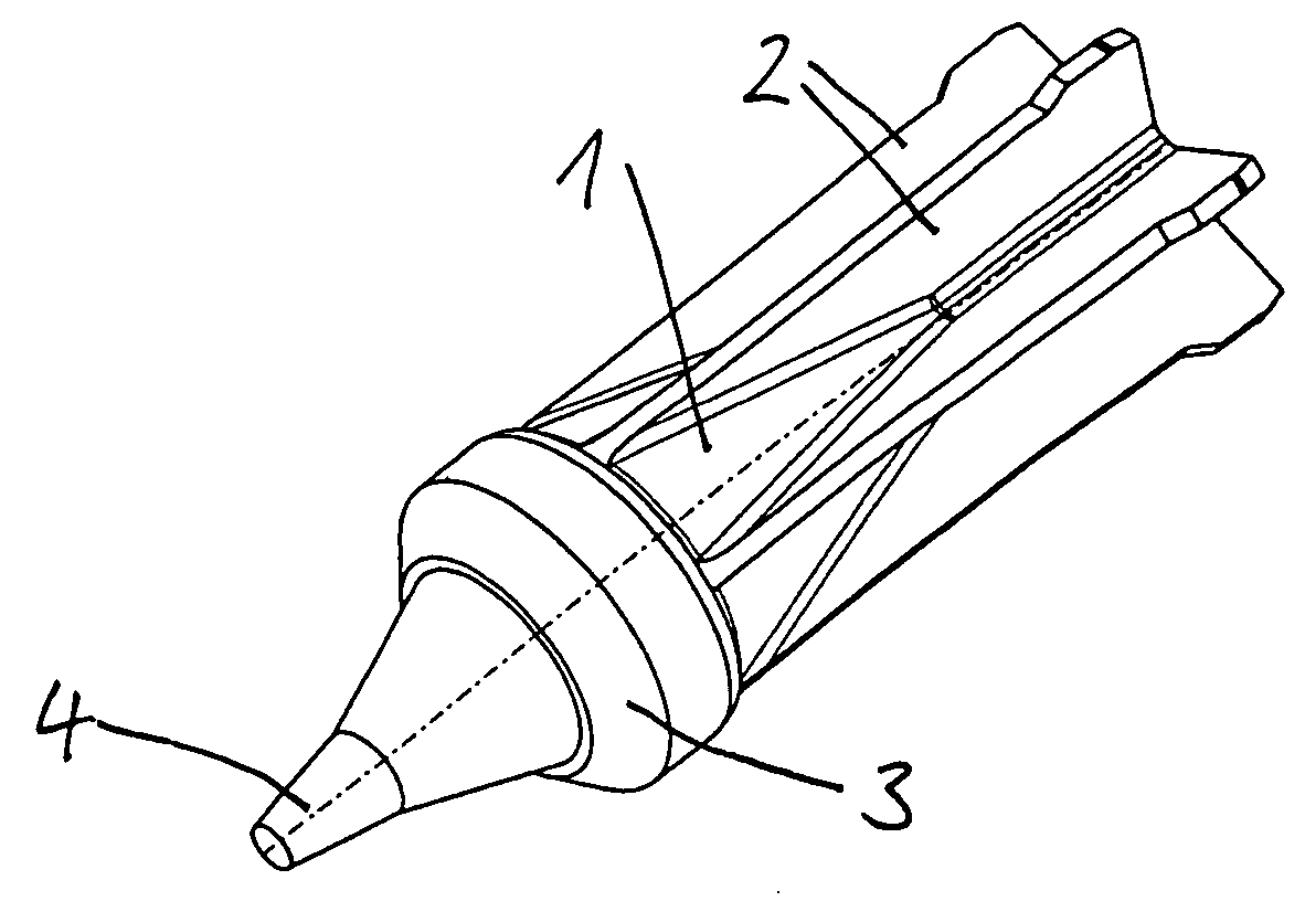
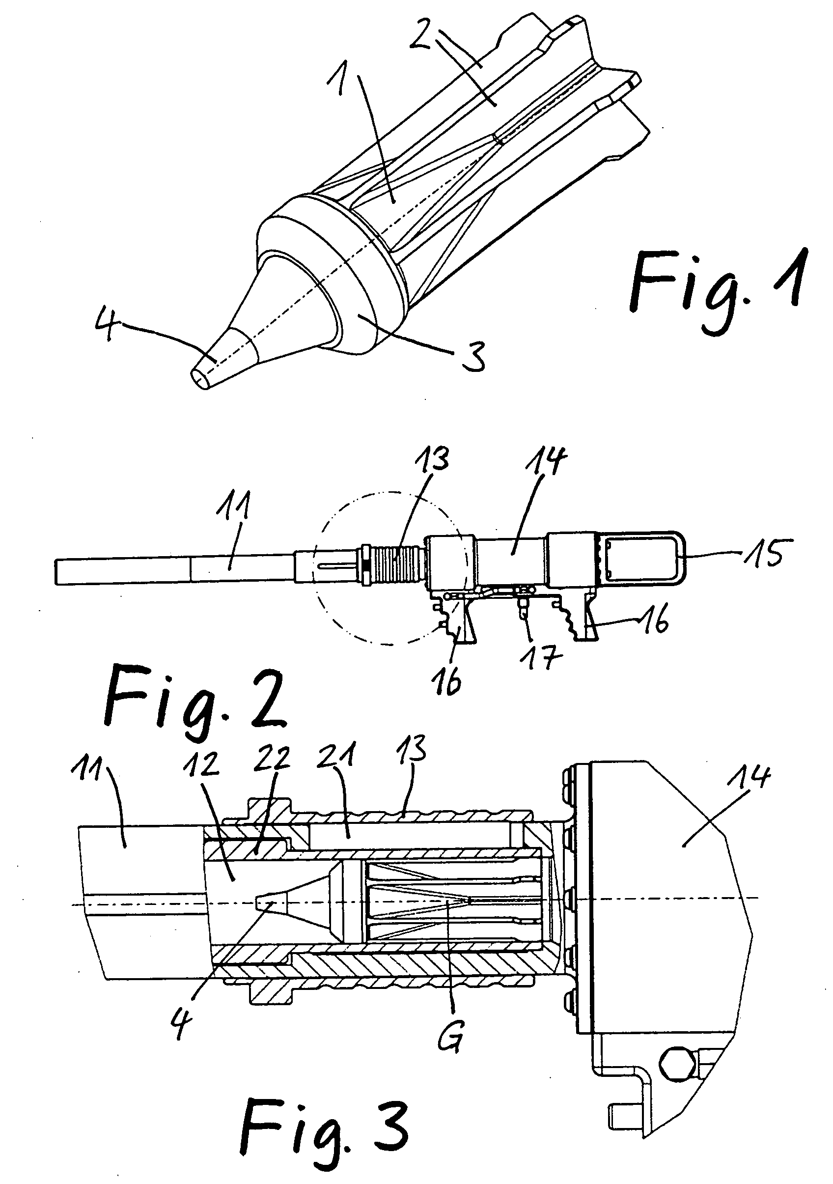
[0029]FIG. 1 shows in a perspective view a shell 1 with an impact detonator for use in connection with the method according to the invention. The shell has for example a diameter of 40 mm and a length of about 130 mm. It comprises a shell body 1 forming a shell sleeve with flight stabilization fins 2, a cover 3 forming the front part and an impact detonator 4 disposed at the front end of the cover 3. The hollow space surrounded by shell body 1 and the cover 3 is filled with a charge of an explosive material or a pyrotechnical material.
[0030]FIG. 2 shows, in a side view, an industrial cannon for shooting shells as shown in FIG. 1. It includes a barrel 11, a shell chamber 12 at the rear end of the barrel 11, which can be closed by an axially movable closure sleeve 13, and a cannon body 14 with a rear carrying handle 13 and operating handles 16 as well as a compressed air connector 17.
[0031]FIG. 3 shows the area of interest of the industrial cannon which is operated by compressed air...
PUM
 Abstract
Description
Claims
Application Information