
Combined electrochemical machining and electropolishing micro-machining apparatus and method

a technology of electrochemical machining and micro-machining, which is applied in the manufacture of electrolysis components, printed circuits, manufacturing tools, etc., can solve the problems of poor surface roughness, unsuitable for most mass production and various products, and slow machining speed, and achieve the effect of fast micro-machining speed

Inactive Publication Date: 2007-06-21
YUAN ZE UNIV
View PDF1 Cites 4 Cited by
  • Summary
  • Abstract
  • Description
  • Claims
  • Application Information

AI Technical Summary

Benefits of technology

[0008] The primary object of the present invention is to provide a combined electrochemical machining and electropolishing micro-machining apparatus and method. In which, its overall micro-machining speed is fast.
[0009] The next object of the present invention is to provide a combined electrochemical machining and electropolishing micro-machining apparatus and method. It can improve the surface roughness significantly.

Problems solved by technology

No matter which kind of machining method is utilized, the traditional methods still have the following disadvantages and problems.
But, its machining speed is very slow.
So, it is not suitable for most mass production and for various products.
[2] The surface roughness is poor.
But, it is easy to create pressure, heat, deformation and / or residual stress problems.
Moreover, after such machining, the surface roughness is poor.
In addition, cooling, debris removing and tool wearing are other major issues need to be solved.
In case it is for micro-machining, the available tools become less and difficult to find.
Under some conditions, it might happen that there is no tool can be used for micro-machining.
[3] It cannot work on an extremely hard metal workpiece.
By using a tool, although the traditional directly-contacting machining speed is fast, it causes the tool wearing problem.
For some extremely-hard metal workpiece, it is possible that no tool can be used.

Method used


Image

  • Combined electrochemical machining and electropolishing micro-machining apparatus and method
  • Combined electrochemical machining and electropolishing micro-machining apparatus and method
  • Combined electrochemical machining and electropolishing micro-machining apparatus and method

Examples


Embodiment Construction

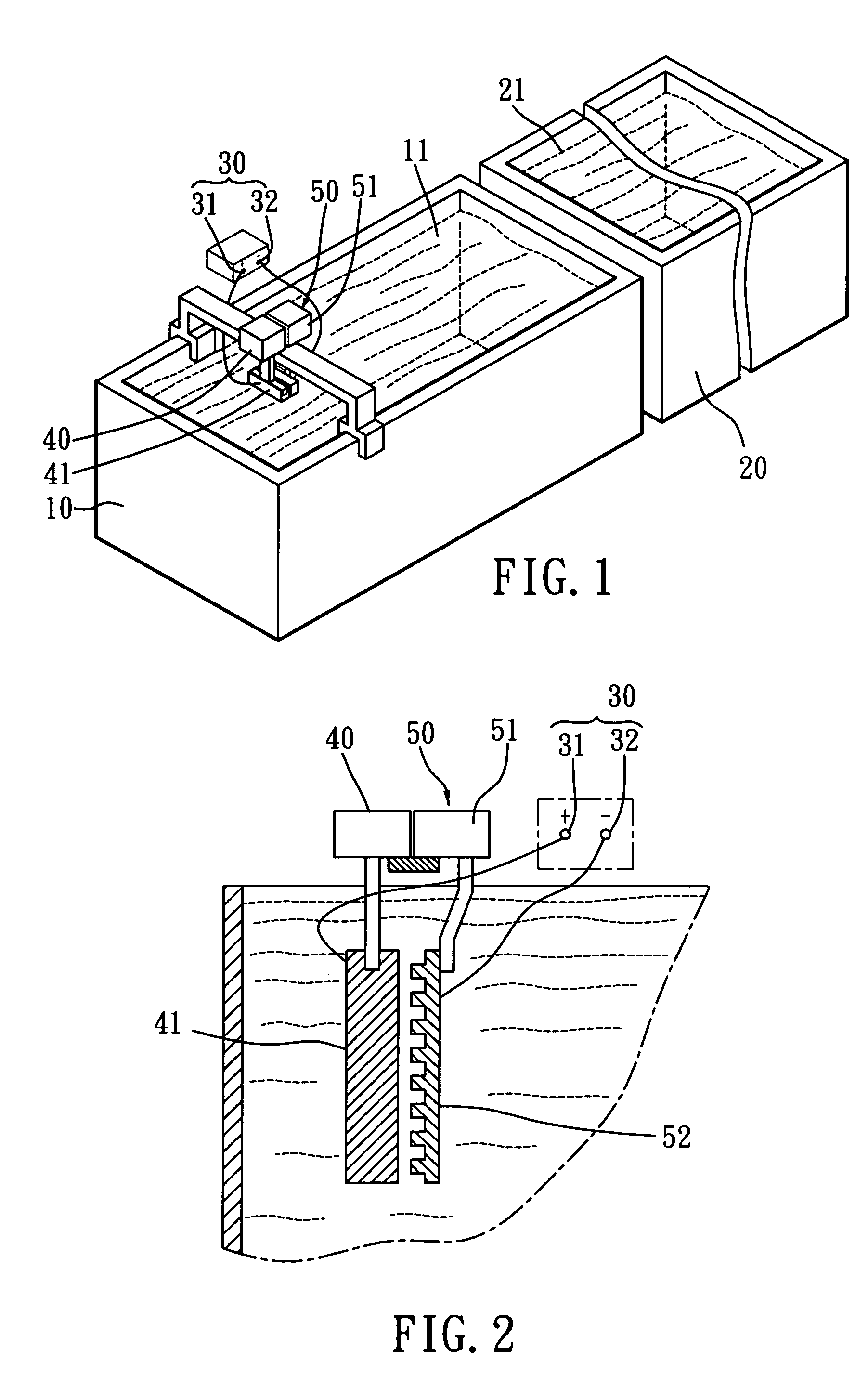
[0031] Referring to FIGS. 1 and 2, the present invention relates a combined electrochemical machining and electropolishing micro-machining apparatus. It comprises:

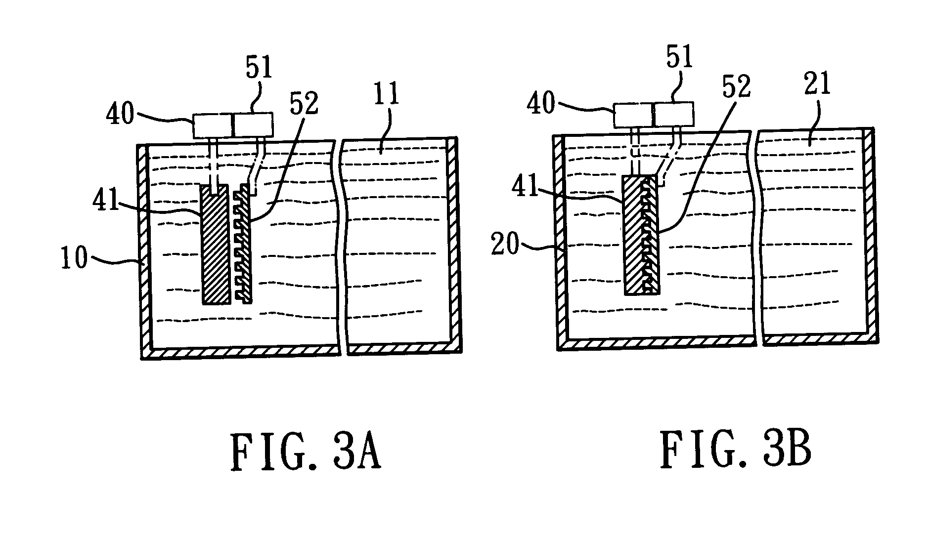
[0032] an electrochemical machining solution container 10 for storing a first working fluid 11; the first working fluid 11 being a neutral solution 11 containing water and salt substance;

[0033] an electropolishing solution container 20 for storing a second working fluid 21; the second working fluid 21 being an acid solution containing water and acid substance;

[0034] a power supplying system 30 having an anode 31 and a cathode 32;

[0035] a metal workpiece holder 40 for securing a metal workpiece 41; the metal workpiece 41 connecting with the anode 31; and

[0036] a mold-plate assembly 50 having: [0037] (a) a micro-movement controller 51; and [0038] (b) a mold-plate portion 52; the mold-plate portion 52 connecting with the cathode 32 and being driven by the micro-movement controller 51;

[0039] so that the metal workpiece 4...


PUM

PropertyMeasurementUnit
Speedaaaaaaaaaa
Surface roughnessaaaaaaaaaa

Abstract

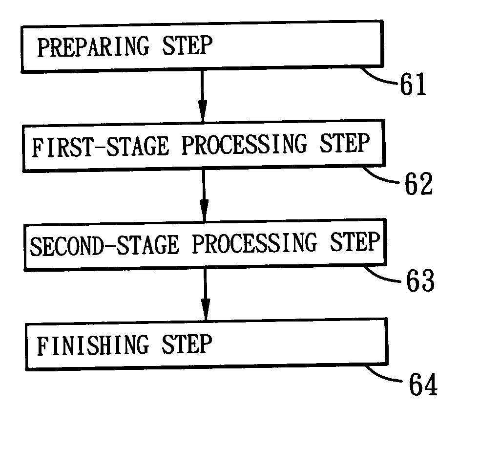
A combined electrochemical machining and electropolishing micro-machining method includes the steps of (1) preparing step, (2) first-stage processing step, (3) second-stage processing step, and (4) finishing step. The apparatus includes an electrochemical machining solution container, an electropolishing solution container, a metal workpiece connecting with an anode, a mold-plate portion connecting with a cathode. Based on this arrangement, the metal workpiece is immersed in a first working fluid to conduct the electrochemical machining process and then to be immersed in a second working fluid to conduct the electropolishing process. So, the overall micro-machining speed is fast. It can improve the surface roughness significantly. It is suitable for extremely hard metal workpiece.

Description

BACKGROUND OF INVENTION [0001] 1. Field of the Invention [0002] The present invention relates to a combined electrochemical machining and electropolishing micro-machining apparatus and method. The overall micro-machining speed is fast. It can improve the surface roughness significantly. It is suitable for extremely hard metal workpiece. [0003] 2. Description of the Prior Art [0004] The traditional machining methods include lathe, mill, plane, grind, drill, etc. However, when a micro-machining is needed, the electroforming method is another possible machining method. No matter which kind of machining method is utilized, the traditional methods still have the following disadvantages and problems. [0005] [1] The overall machining speed is relative slow. As the need for micro-machining increases in recent years, the electroforming method is a possible solution. But, its machining speed is very slow. So, it is not suitable for most mass production and for various products. [0006] [2] The...

Claims


Application Information

Patent Timeline
IPC IPC(8): B23H5/02
CPCB23H3/00B23H3/08C25F3/16
Inventor LEE, SHUO-JENLAI, JIAN-JANGLEE, YU-MING
Owner YUAN ZE UNIV
Learn More