Antiglare film and image display

a technology applied in the field of antiglare film and image display, can solve the problems of unevenness as intended, increase in cost, and significant deterioration of image display visibility, and achieve excellent antiglare performance and prevent visibility from lowering

Active Publication Date: 2007-06-21
SUMITOMO CHEM CO LTD
View PDF3 Cites 23 Cited by
  • Summary
  • Abstract
  • Description
  • Claims
  • Application Information

AI Technical Summary

Benefits of technology

[0015] The present invention is to provide an antiglare film having excellent antiglare performance even in a state where a low reflection film does not exist on the outermost surface, which sufficiently prevents visibility from lowering due to discoloring to white or glare, and furthermore, to provide an image display to which such an antiglare film is applied.

Problems solved by technology

Visibility of image displays, such as liquid crystal displays, plasma displays, Braun tube (cathode ray tube: CRT) displays and organic electroluminescence (EL) displays is significantly deteriorated when external light is reflected from the display surface.
From among these, it is necessary to form a multilayer film having a uniform optical film thickness in the former anti-reflection film, and therefore, the cost increases.
However, the arrangement and form of the unevenness on antiglare films manufactured by dispersing such a filler are influenced by the state of distribution of the filler in the resin solution or the state of application, and therefore, unevenness as intended may not sufficiently performed, and sufficient antiglare performance may not be gained.
Furthermore, in the case where such a conventional antiglare film is placed on the surface of an image display, the entirety of the display surface becomes whitish due to scattering of light, causing that the surface becomes of a cloudy color, that is to say, so-called discoloring to white easily occurs.
Such “glaring” lowers the visibility of the displayed image.
In this technique, the composition of the ionizing radiation curing resin solution that can be used is restricted, and leveling, such as through application of a liquid distilled with a solvent, may be expected to be insufficient, and therefore, the uniformity of the film thickness may not be sufficient.
Furthermore, it is necessary to fill the engraving emboss roll directly with a resin liquid, and therefore, high physical precision is required in the engraving emboss roll in order to secure uniformity on the uneven surface, and thus, it is difficult to fabricate an emboss roll.
In the state where a blasting process has been carried out on the surface of the emboss roll as described above, distribution in the diameter of unevenness corresponds to the distribution in the particle diameter of the blasting particles, and it is difficult to control the depth of recesses gained through blasting, and thus, it may be difficult to gain unevenness in a form which is excellent in antiglare performance with high reproducibility.
In this method for fabricating an emboss roll, blasting or shooting is carried out on the chromium plating having a high hardness, and therefore, it is difficult for unevenness to be created, as well as for the form of the created unevenness to be controlled with precision.
Furthermore, the surface of the chromium plating generally tends to be coarse, and fine unevenness is created through chromium plating on the unevenness created through blasting, and therefore, it is difficult to design the manner in which unevenness is created.
Moreover, the scattering properties in the finally gained antiglare film change in a negative manner due to the fine unevenness created through chromium plating.

Method used


Image

  • Antiglare film and image display
  • Antiglare film and image display
  • Antiglare film and image display

Examples


example 1

[0123] The surface of an aluminum roll (A5056 according to JIS) having a diameter of 300 mm was polished to a mirror surface. Zirconia beads “TZ-SX-17”, made by Tosoh Corporation (trademark, having an average grain diameter of 20 mm), were blasted onto the outer surface of the gained aluminum roll polished to a mirror surface under a pressure for blasting at 0.1 MPa (gauge pressure, same as in the following), using a blasting apparatus (gained from Fuji Manufacturing Co., Ltd.) so that unevenness was created on the surface. An electroless gloss nickel plating process was carried out on the gained uneven aluminum roll, and thus, a metal mold was fabricated. The thickness of the plating was set at 15 μm, and the thickness of the plating was measured after plating using a β ray film thickness measuring instrument (trademark: “Fisher Scope MMS”, gained from Fischer Instruments K.K.) so as to find that the thickness was 17.2 μm.

[0124] Separately, a photo-curing resin composite “GRANDIC ...

examples 2 to 6

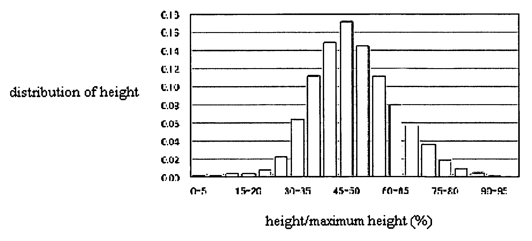
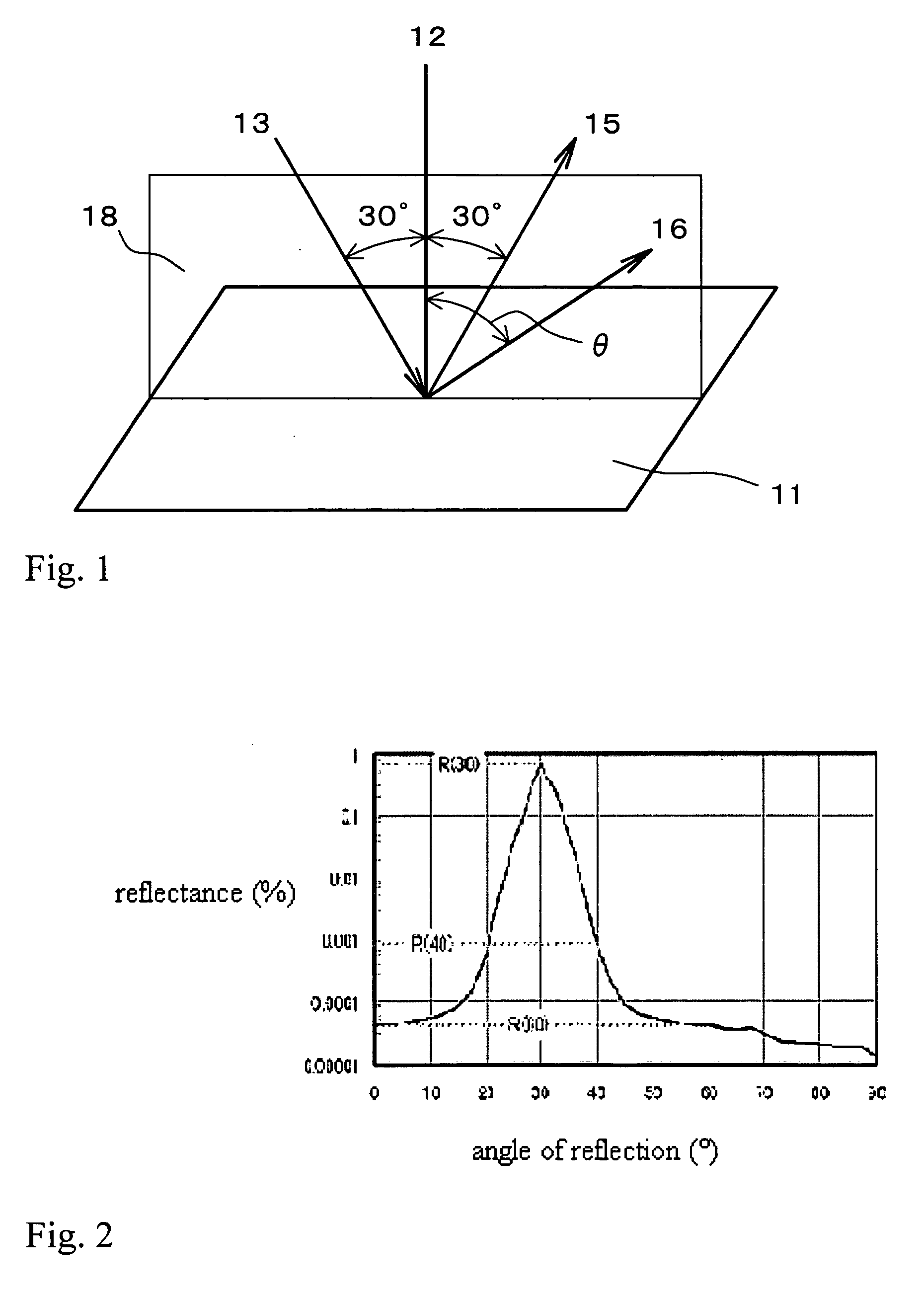
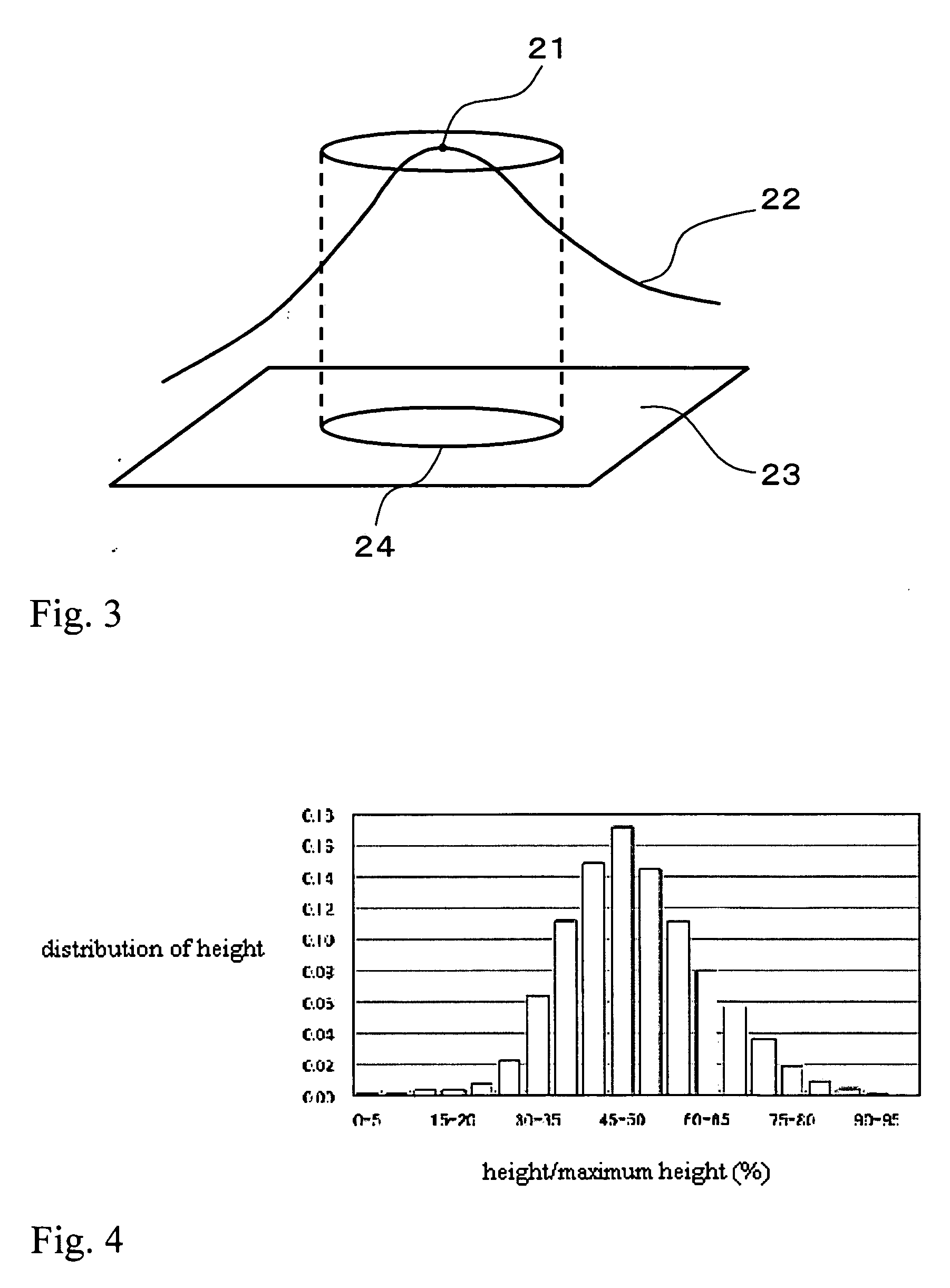
[0126] Metal molds with various plating thickness having unevenness on the surface as shown in Table 1, and with other factors being the same as in Example 1, were fabricated. Transparent antiglare films, which are multilayer bodies made of a cured resin having unevenness on the surface and a TAC film, were fabricated in the same manner as in Example 1, using the respective molds. Optical properties of the gained antiglare films are shown in Table 1, and the results of the evaluation of the form of the uneven surface and the antiglare performance are shown in Table 2, respectively. In addition, as for Example 2, a graph of the reflection profile is shown in FIG. 10 together with the results of Example 1, and the histogram of height is shown in FIG. 11 together with the results of Example 1, respectively. As for Examples 3 and 4, the graphs of the respective reflection profiles are shown in FIG. 12, and the histograms of height are shown in FIG. 13, respectively, and in addition, as ...


PUM


Abstract

The present invention provides an antiglare film having the reflectance at an angle of reflection of 30° for incident light 13 at an incident angle of 30° of not more than 2%, and the reflectance of not more than 0.003% at an angle of reflection of 40° in an antiglare film which also satisfies any of the following (1) to (5): (1) 50 to 150 protrusions are provided within a region of 200 μm×200 μm; (2) when the height of each point on the uneven surface is shown in a histogram, the peak exists in a range between +20% and −20% with the middle point between the highest point and the lowest point at the center; (3) the arithmetic average height Pa on the surface is 0.08 μm to 0.15 μm; (4) the maximum height in a cross section Pt on the surface is 0.4 μm to 0.9 μm; and (5) the average area of the polygons is 300 μm2 to 1000 μm2 when Voronoi division is carried out on the surface of the film with the peaks of these protrusions as generating points.

Description

BACKGROUND OF THE INVENTION [0001] 1. Technical Field [0002] The present invention relates to an antiglare film having little haze and excellent antiglare properties, as well as an image display with such an antiglare film. [0003] 2. Background of the Invention [0004] Visibility of image displays, such as liquid crystal displays, plasma displays, Braun tube (cathode ray tube: CRT) displays and organic electroluminescence (EL) displays is significantly deteriorated when external light is reflected from the display surface. In order to reduce such reflection of external light, a layer for reducing reflection of external light is laminated on the surface of conventional image displays, such as those of television sets and personal computers, of which the image quality is important, video cameras and digital cameras used outdoors, where external light is strong, and cellular phones, which display using reflected light. The layer can be generally categorized into two kinds, such as one o...

Claims


Application Information

Patent Timeline
Patent Type & Authority Applications(United States)
IPC IPC(8): G02B5/08G02B17/00
CPCY10T428/24355G02B1/111G02B5/02
Inventor FURUYA, TSUTOMUKUWABARA, MASATO
Owner SUMITOMO CHEM CO LTD
Why Eureka
Try Eureka